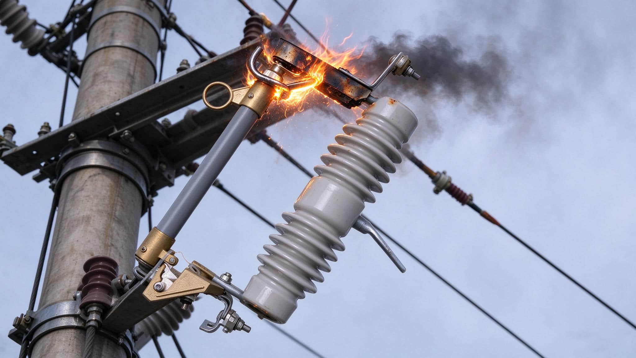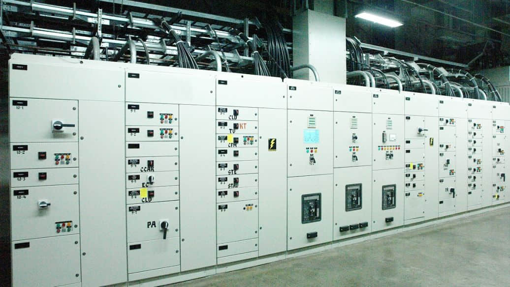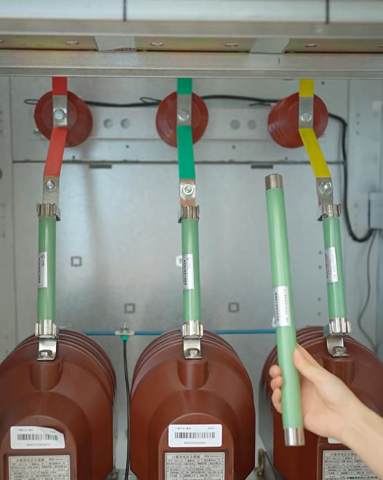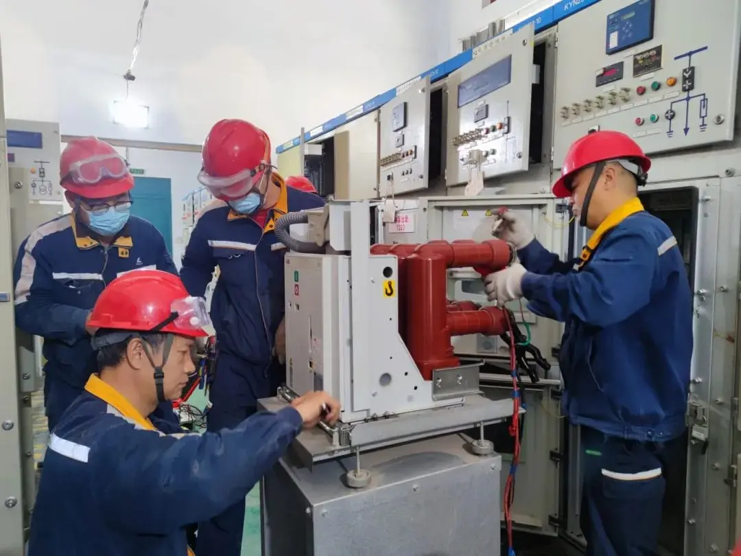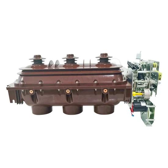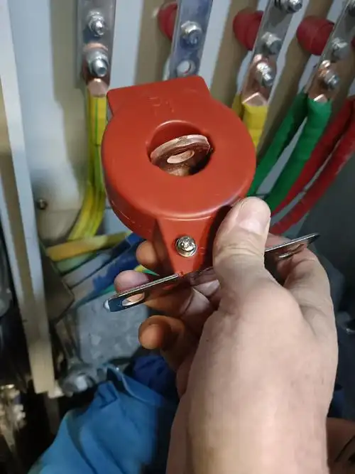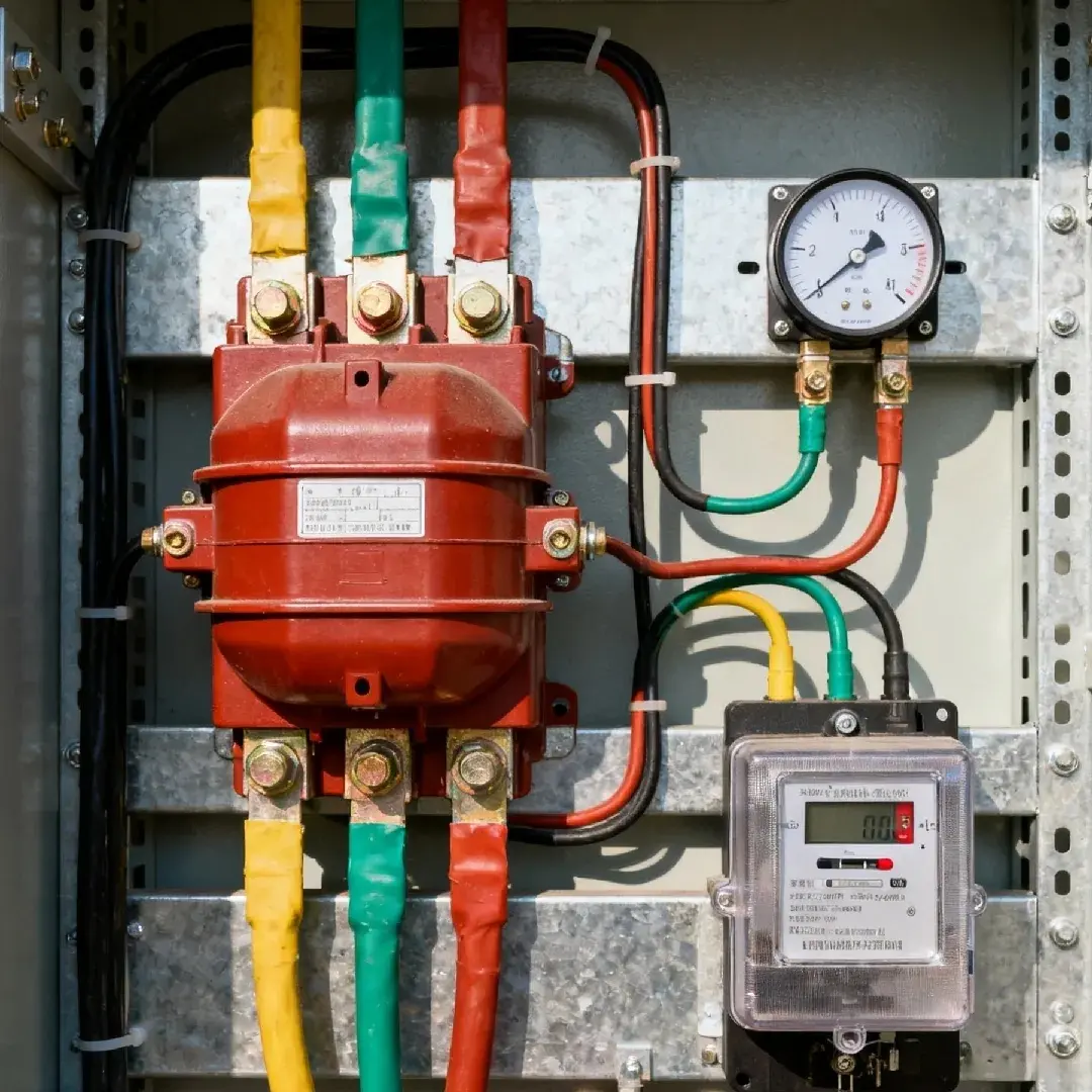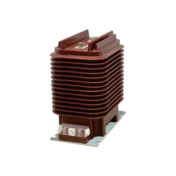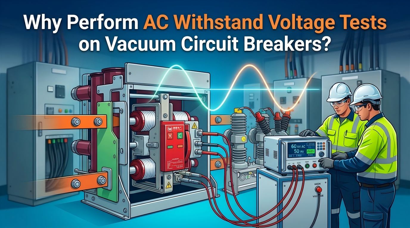
A vacuum circuit breaker can appear perfectly normal from the outside, show acceptable contact action, and even pass a basic insulation resistance check—yet still hide an insulation defect serious enough to cause flashover the moment it is energized.
That is exactly why the vacuum circuit breaker dielectric withstand test remains one of the most decisive field tests in medium-voltage maintenance. For utilities, industrial plants, substations, and service contractors, this is not just another routine checkbox. It is often the last hard proof that an Indoor vacuum circuit breaker or Outdoor Vacuum Circuit Breaker is actually safe to place into service.
The Hidden Risk: A Vacuum Circuit Breaker Can Look Fine and Still Fail
Insulation defects are often invisible. Moisture film, surface contamination, aging support insulation, assembly stress after repair, and damaged cable terminations may not leave obvious visual clues.
In the field, failures rarely announce themselves politely. They show up as sudden outage events, bus faults, feeder trips, internal discharge, or safety incidents during energization.
This is especially true for medium-voltage switchgear. A 10 kV vacuum circuit breaker may sit in storage for months, survive transport, and still develop insulation weakness from humidity, dust deposition, or handling damage. The breaker can still open and close mechanically, which misleads less experienced crews into thinking the unit is healthy.
What matters is whether the insulation system can withstand real operating stress. That question is answered far more directly by AC withstand testing than by appearance alone.
What Problem Does AC Withstand Voltage Testing Solve?
An AC withstand voltage test is the most direct, most stringent, and most practical way to verify insulation strength under realistic power-frequency conditions. It evaluates whether the insulation system can survive the electrical stress it will actually face during operation.
That is why this test has long been treated as a determining acceptance method before commissioning and as a critical tool in preventive maintenance testing for vacuum circuit breakers.
Unlike low-stress screening methods, AC high-potential testing for vacuum interrupters applies a meaningful dielectric challenge. It does not merely estimate insulation condition. It proves whether the breaker can tolerate a specified overvoltage for a defined time.
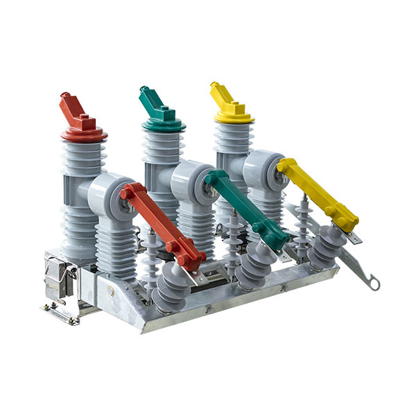
Why AC Withstand Voltage Tests Matter for Vacuum Circuit Breakers
For vacuum circuit breakers, the AC withstand test has a very practical purpose: it reveals whether hidden insulation weaknesses will fail under industrial-frequency electrical stress before the breaker is exposed to actual system duty.
Verifies real insulation performance under operating frequency
The strongest technical advantage of the power frequency withstand voltage test procedure is that the voltage waveform, frequency, and internal insulation voltage distribution closely match actual service conditions.
That matters in real equipment. Insulation does not always behave the same way under DC screening as it does under AC stress. Internal electric field distribution, surface leakage behavior, and weak point response are more representative under power-frequency conditions.
Detects hidden defects that insulation resistance alone may miss
A megohmmeter is useful, but it is only a first filter. It may identify severe moisture ingress or gross insulation deterioration, yet still miss localized defects.
Examples include:
Surface contamination on support insulation
Moisture trapped in interfaces or crevices
Carbonized tracking paths beginning to form
Assembly defects after overhaul
Partial insulation damage caused by transport vibration
Weak clearances caused by improper lead routing
These defects may remain quiet during insulation resistance testing but become active under insulation integrity testing of medium voltage circuit breakers with AC voltage applied at the proper level.
Confirms ability to withstand power-frequency overvoltage
For 10 kV class breakers, the test directly checks the equipment’s ability to withstand industrial-frequency overvoltage. This is not theoretical.
In practical maintenance work, a breaker that cannot survive this condition is not fit for dependable operation. If it fails in the test yard, that is a controlled event. If it fails in service, the consequences can include switchgear damage, production loss, arc risk, and feeder outage.
Requires relatively low test transformer capacity
One practical benefit often appreciated by field personnel is that the required transformer capacity is relatively low. In many cases, a small-capacity test PT or compact AC withstand test set is sufficient to generate the required industrial-frequency test voltage for a vacuum circuit breaker.
That makes the method efficient as well as authoritative. It delivers high diagnostic value without demanding excessively large test equipment.
AC Withstand Voltage Test vs Insulation Resistance Test
These two tests are related, but they are not interchangeable.
Insulation resistance testing with a 2500 V megohmmeter screens the basic condition of the insulation system. It is fast, useful, and essential before further testing. However, it does not fully prove the breaker can endure operating-frequency overvoltage stress.
AC withstand voltage testing is the higher-level proof test. It demonstrates whether the insulation remains stable when subjected to a specified AC electric field for a defined hold time.
A simple way to explain it in the field is this:
The megohmmeter tells you whether the insulation is obviously bad.
The AC withstand test tells you whether the insulation is truly strong enough for service.
Experienced technicians know that passing the first test does not guarantee passing the second. That distinction is critical and often misunderstood by teams with limited medium-voltage experience.

When Should You Perform AC Withstand Voltage Testing on a Vacuum Circuit Breaker?
Search intent around Indoor vacuum circuit breaker and Outdoor Vacuum Circuit Breaker testing usually comes from maintenance teams facing one of a few standard scenarios. In actual utility and industrial practice, AC withstand testing is commonly required in the following situations.
Before first commissioning
This is one of the most important applications. Before energization, the test determines whether the breaker is fit to enter service.
That is why many maintenance procedures treat it as decisive. A new breaker can still have shipping damage, installation contamination, or assembly issues.
After overhaul, repair, or component replacement
Any work that interrupts the insulation structure requires re-verification. If bushings, insulating supports, wiring, vacuum interrupter assemblies, or related components were disturbed, the dielectric condition must be checked again.
Mechanical completion is not electrical proof. The breaker may be properly assembled and still have an insulation weakness introduced during maintenance.
During preventive maintenance programs
In scheduled reliability programs, this test plays an essential role in preventive maintenance testing for vacuum circuit breakers. It helps detect emerging defects before they become outages.
Trend comparison also becomes valuable over time. A breaker that repeatedly passes with stable pre-test insulation resistance and normal withstand behavior builds confidence in its condition history.
After abnormal events
Abnormal conditions should trigger special attention. Typical triggers include:
Fault interruption under severe conditions
Moisture ingress
Flooding or condensation exposure
Heavy dust or contamination buildup
Long-term storage
Transportation shock
Visible tracking marks or unusual odor
Suspected insulation contact with foreign objects
If any of these conditions exist, the breaker should not be assumed healthy based only on mechanical checks.
Test Standards and Typical Acceptance Basis
The acceptance basis should always follow the applicable preventive test code, manufacturer instructions, utility standards, and site-approved procedures. In many practices, the AC test voltage is taken as 0.8 times the specified withstand value according to DL/T 593 or an equivalent local requirement.
For example, a practical field value often cited for a 10 kV breaker is 33.6 kV. This is not a universal number for all ratings and standards, but it is a common real-world example when applying the 0.8 rule to the corresponding specified withstand level.
Good engineers never rely on memory alone. They verify the rating, standard basis, equipment type, and site procedure before applying voltage.
Pre-Test Preparation for Vacuum Circuit Breaker AC Withstand Voltage Testing
Preparation determines whether the test is safe, valid, and repeatable. In many field failures, the root cause is not the test set itself but poor pre-job control.
Before any voltage is applied, the crew should confirm instruments, documents, environmental conditions, work isolation, temporary grounding arrangements, and role assignments.
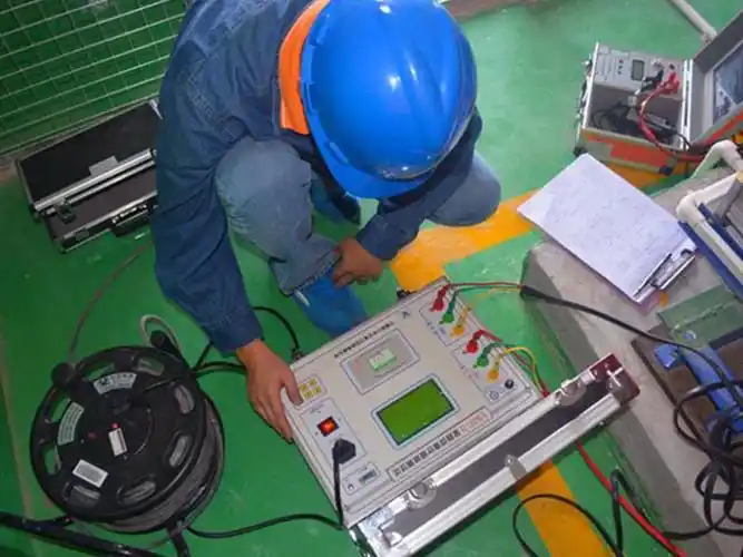
Required instruments and tools
The basic test package should include the following:
2500 V megohmmeter
AC withstand test set or AC hipot test equipment
Test leads with verified insulation condition
Grounding rod or discharge rod
Grounding conductors
Thermometer and hygrometer
Calculator
Portable power supply if required
Hand tools
Safety belt where applicable
PPE and barricade accessories
Field teams using quality switchgear from manufacturers such as Weisho Electric still need the same discipline. Good equipment does not eliminate the need for correct test preparation.
Required documents and records
The test should never begin without proper references and documentation. At minimum, prepare:
Preventive test regulations or approved standard procedure
Work forms and test records
Breaker nameplate data
Wiring identification data
Historical test results for comparison
Approved work permit and isolation confirmation
Historical records are especially useful. A single pass result is valuable, but a multi-year comparison is much more powerful for diagnosing insulation trends and maintenance quality.
Environmental and safety checks
Temperature and humidity must be recorded. Grounding condition must be verified. The equipment must be correctly isolated from the system and clearly identified.
In addition, crews should confirm:
No unintended backfeed path exists
Test area barricades are in place
Personnel roles are clearly assigned
A responsible person will cross-check the wiring before energization
The correct breaker position for the intended test has been confirmed
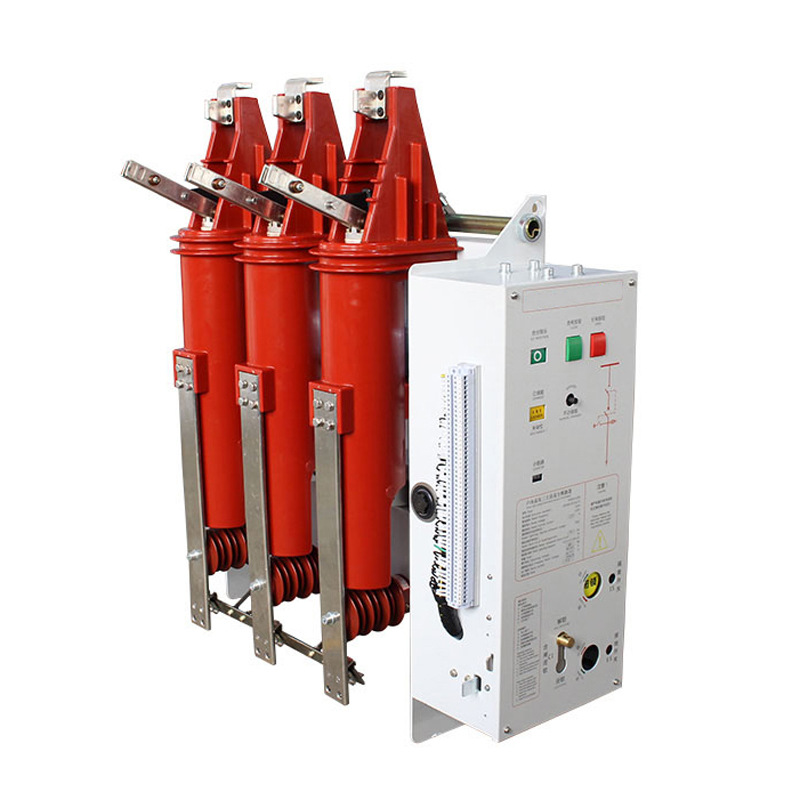
Step-by-Step Power Frequency Withstand Voltage Test Procedure
The sequence below reflects standard field practice for a vacuum circuit breaker dielectric withstand test. It is based on the operating logic outlined in established preventive testing procedures.
Step 1: Measure insulation resistance first
Use a 2500 V megohmmeter to measure insulation resistance before the AC test. Connect the test lead, grounding lead, and shielding connection correctly where required.
The connections must be secure. Poor contact, incorrect output terminal use, or missing shielding in a leakage-sensitive setup can distort the result and mislead the crew.
This first step is not optional. It is both a safety check and a condition screen before higher voltage is applied.
Step 2: Connect the AC test circuit correctly
Correct test wiring is essential.
When the breaker is in the open position, one side of the three phases is shorted together and connected to the high-voltage test source. The other side, together with the enclosure, is grounded.
When the breaker is in the closed position, the enclosure remains grounded. The exact test connection must follow the approved procedure for the breaker structure and test purpose.
After the wiring is complete, the responsible person must verify the full circuit before any voltage rise begins.
Step 3: Raise voltage from zero only
This is a strict operational rule: voltage must be raised from zero. Shock closing or sudden application of full voltage is prohibited.
This is not a formality. A sudden surge can create unnecessary stress, misreadings, or dangerous test behavior. Controlled rise is part of the test validity and part of personnel safety.
Step 4: Apply the specified test voltage and hold for 1 minute
The test voltage should follow the applicable standard basis. Using the example given above, a 10 kV breaker may be tested at 33.6 kV, derived from 0.8 times the specified value.
During voltage rise, the speed may be somewhat faster up to around 75% of the test voltage. After that point, the voltage should be increased uniformly at approximately 2% of test voltage per second until the target value is reached.
Once the specified value is reached, maintain the voltage for 1 minute.
Step 5: Observe current, voltage, sound, and visible condition
The operator must watch the instruments continuously. This is not the time to look away, discuss unrelated work, or move around the yard.
Pay close attention to:
Current stability
Voltage stability
Visible flashover
Smoke
Breakdown signs
Internal discharge sound
Unexpected meter swing
If flashover, smoke, insulation collapse, or abnormal discharge is observed, the test must be stopped immediately by reducing the voltage and isolating the source.
Step 6: Reduce voltage uniformly and discharge fully
When the hold time is complete, do not simply cut power abruptly under load. Return the regulator to zero uniformly within a few seconds, then disconnect the power source.
After that, discharge the equipment first through a resistor-type discharge rod or high-resistance discharge path, and then apply direct grounding.
This final step is essential because residual charge can remain on the equipment and present a severe shock hazard.
Typical Test Data Table for a 10 kV Vacuum Circuit Breaker
The following table gives a practical example for field reference. Actual values must always follow the applicable standard, breaker rating, and approved site procedure.
| Item | Typical Example |
|---|---|
| Equipment type | 10 kV indoor or outdoor vacuum circuit breaker |
| Pre-test insulation resistance | Measured with 2500 V megohmmeter |
| AC test basis | 0.8 × specified value per applicable standard |
| Example test voltage | 33.6 kV |
| Voltage rise method | From zero; faster below 75%, then slower and uniform near final value |
| Final rise rate | About 2% of test voltage per second |
| Withstand duration | 1 minute |
| Pass criteria | No flashover, no breakdown, no sudden meter change, no internal discharge sound |
Test Preparation Checklist Table
This fast-reference checklist mirrors what experienced test crews actually verify before energization.
| Category | Key Checkpoints |
|---|---|
| Instruments | Megohmmeter, AC hipot tester, leads, discharge rod |
| Safety tools | Grounding leads, PPE, safety belt, barricades |
| Site conditions | Isolation confirmed, grounding reliable, humidity recorded |
| Documentation | Test forms, standards, historical records, nameplate data |
| Personnel | Responsible person assigned, wiring cross-check completed |
Common Mistakes and Correct Measures Table
Most field problems during AC withstand testing are procedural, not mysterious. The table below summarizes the errors seen most often.
| Common Mistake | Correct Measure |
|---|---|
| Test circuit not rechecked | Raise voltage only after the responsible person confirms wiring |
| Incorrect voltage rise method | Start from zero and raise uniformly |
| Incomplete voltage reduction | Return regulator evenly to zero before power-off |
| No discharge after test | Fully discharge the breaker and test object |
| Temporary shorts or grounds left installed | Remove all temporary connections and inspect the site |
How to Judge Whether the Vacuum Circuit Breaker Passed
Pass or fail should be judged using clear operational criteria, not guesswork.
Pass indicators
A breaker is generally considered qualified when the applied voltage is held for 1 minute and the current and voltage remain stable, with no flashover, no breakdown, no sudden meter change, and no internal discharge sound.
This indicates that the insulation system remained intact under the required AC stress.
Failure indicators
Failure indicators include:
Flashover
Smoke
Visible discharge
Insulation collapse or puncture
Abnormal sound from inside the breaker
Sudden current or voltage instability
If any of these occur, the voltage must be reduced immediately, the power source disconnected, and the breaker inspected before any retest is considered.
Post-Test Actions and Record Management
The test is not complete when the voltage is removed. Good post-test discipline is what makes the result traceable, defensible, and safe.
Complete and verify all records
All work forms should be checked for completeness and accuracy. Record the temperature, humidity, breaker nameplate data, test items, measured values, acceptance conclusion, and signatures of the responsible person and test personnel.
Incomplete records create problems later. If an outage investigation happens months afterward, undocumented test data is almost the same as no test data.
Restore the breaker and remove all temporary leads
All self-installed shorting wires, grounding leads, and test leads must be removed. The tested equipment should be restored to the condition it was in before the test, unless another approved work step follows.
The breaker itself should be visually checked again. The site should be cleaned, tools counted, and no temporary connection should remain in place.
Close out work with operations personnel
The final work closeout should be completed together with operations personnel or the designated system owner. Both parties should confirm that the breaker has been restored to its pre-test status and is safe for the next step.
Digital record entry into the maintenance management system should then be completed, and the final conclusion should be signed off.
Real-World Example: Why This Test Prevents Costly Failures
Consider a common field scenario in a 10 kV industrial distribution room. A feeder breaker had been removed during shutdown maintenance, stored temporarily, and reinstalled before restart.
The breaker passed mechanical checks. It also produced a seemingly acceptable insulation resistance reading using a 2500 V megohmmeter.
At that point, an inexperienced crew might have been tempted to energize it. Instead, the team performed the required AC high-potential testing for vacuum interrupters.
During the rise toward the target voltage, the meters remained normal at first. Near the upper portion of the test level, however, an abnormal internal discharge sound appeared. The voltage was reduced immediately, and the breaker was removed for inspection.
The cause turned out to be contamination and moisture residue on an insulating support surface introduced during maintenance handling. At low test stress, it did not show clearly. Under operating-frequency high-voltage stress, it did.
The cost of catching that defect in the test area was minor: extra cleaning time, inspection labor, and a delayed return to service by a few hours. The cost of missing it could have included a feeder trip, unplanned plant downtime, switchgear damage, and safety exposure for nearby personnel.
This is why experienced engineers insist on this test. It converts unknown risk into a verified condition.
Indoor vs Outdoor Vacuum Circuit Breaker Testing Considerations
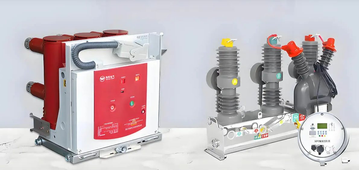
The basic power frequency withstand voltage test procedure is similar for indoor and outdoor units, but the risk profile is not exactly the same.
Indoor vacuum circuit breaker considerations
An Indoor vacuum circuit breaker is generally more protected from rain and direct environmental exposure, but that does not mean the insulation system is risk-free.
Indoor units commonly suffer from:
Dust accumulation
Condensation in poorly ventilated switch rooms
Aging insulation surfaces
Maintenance-related contamination
Improper storage of spare units
Many indoor breaker failures are human-factor failures rather than weather failures.
Outdoor vacuum circuit breaker considerations
An Outdoor Vacuum Circuit Breaker faces additional exposure to moisture, pollution, salt, industrial contaminants, and thermal cycling.
That means more attention should be paid to:
Surface cleanliness
Bushing condition
Water ingress signs
Weathered insulation components
Tracking marks on exposed insulation
Outdoor units often require stricter visual inspection and better environmental judgment before testing. A wet or heavily contaminated surface can distort results or create preventable flashover risk.
Whether the breaker is installed indoors or outdoors, crews should still follow the same disciplined sequence of insulation screening, correct wiring, controlled voltage rise, observation, discharge, and restoration.
Best Practices for Preventive Maintenance Testing of Vacuum Circuit Breakers
The difference between a routine test and a high-quality test usually comes down to consistency. The following best practices separate reliable maintenance programs from paperwork-driven ones.
Always compare with historical data. A pass result is good, but a trend tells the fuller story.
Do insulation resistance first. It is the right screen before applying AC high voltage.
Record temperature and humidity. Environmental context matters when interpreting results.
Cross-check test wiring. One independent verification step prevents many dangerous errors.
Raise voltage gradually from zero. This protects both the equipment and the validity of the test.
Watch the instruments continuously. Small abnormal changes can be early warning signs.
Discharge through resistance and then ground directly. Never skip the discharge step.
Remove all temporary grounds and shorts after the test. Site restoration is part of the job.
Use approved procedures, not memory. Standards and breaker designs vary.
Choose dependable equipment sources. Consistent manufacturing quality from companies such as Weisho Electric supports easier long-term maintenance, though testing discipline remains essential.
In well-run programs, insulation integrity testing of medium voltage circuit breakers is not treated as an isolated event. It is part of a complete reliability strategy that includes visual inspection, mechanical evaluation, record management, and disciplined safety control.
FAQ
What is the purpose of an AC withstand voltage test on a vacuum circuit breaker?
Its purpose is to verify whether the breaker insulation can safely withstand power-frequency overvoltage under realistic operating conditions. It is the most direct and stringent method for confirming insulation strength before energization or during preventive maintenance.
Is insulation resistance testing enough for a vacuum circuit breaker?
No. Insulation resistance testing is only a screening tool that checks the basic condition of insulation. It does not replace AC high potential testing for vacuum interrupters, which proves whether the insulation can tolerate higher AC stress without flashover or breakdown.
What is the typical AC test voltage for a 10 kV vacuum circuit breaker?
The exact value depends on the applicable standard, equipment rating, and utility procedure. A common practical example is 33.6 kV, based on applying 0.8 of the specified withstand level according to the governing acceptance basis.
How long should the AC withstand voltage be applied?
The standard hold time is commonly 1 minute, unless a different approved procedure or equipment-specific instruction is specified.
What happens if flashover or abnormal sound occurs during the test?
The voltage must be reduced immediately, the power disconnected, and the breaker inspected before any retest. Flashover, smoke, breakdown, or abnormal internal discharge sounds are failure indicators and must never be ignored.
Should indoor and outdoor vacuum circuit breakers be tested differently?
The core procedure is similar, but Outdoor Vacuum Circuit Breaker units need extra attention to contamination, moisture, and surface condition. Indoor vacuum circuit breaker units may still have problems related to dust, condensation, aging, or maintenance errors.
Why must the breaker be discharged after the test?
Residual charge can remain on the equipment after high-voltage testing. If the breaker is not safely discharged and grounded, that stored energy can create a serious electric shock hazard for personnel.
Conclusion: AC Withstand Testing Is the Final Proof of Insulation Reliability
The AC withstand voltage test is more than a procedural requirement. It is the final proof that a vacuum circuit breaker has the insulation strength needed for safe and reliable operation.
It verifies real service-frequency performance, reveals hidden defects that a megohmmeter alone may miss, confirms tolerance to power-frequency overvoltage, and supports better commissioning and maintenance decisions for both Indoor vacuum circuit breaker and Outdoor Vacuum Circuit Breaker applications.
When performed correctly—starting with insulation resistance measurement, followed by proper connection, controlled voltage rise, one-minute hold, careful observation, uniform reduction, full discharge, and disciplined recordkeeping—it becomes one of the most effective safeguards in medium-voltage asset management.
That is why experienced field teams do not treat it casually. They treat it as the decisive checkpoint between assumption and proof.
CTA: Need a Reliable Vacuum Circuit Breaker Test Procedure or Checklist?
If you need a field-ready checklist, a standardized vacuum circuit breaker dielectric withstand test procedure, or guidance for commissioning and preventive maintenance testing for vacuum circuit breakers, now is the time to get a document your team can actually use on site.
Request a practical AC withstand voltage testing checklist for your next job, compare it against your current maintenance workflow, and make sure every breaker test is done with the consistency, safety, and technical rigor that medium-voltage systems demand.
Do not wait for a hidden insulation defect to reveal itself during energization. Put a proven AC withstand test procedure in your team’s hands before the next breaker goes into service.