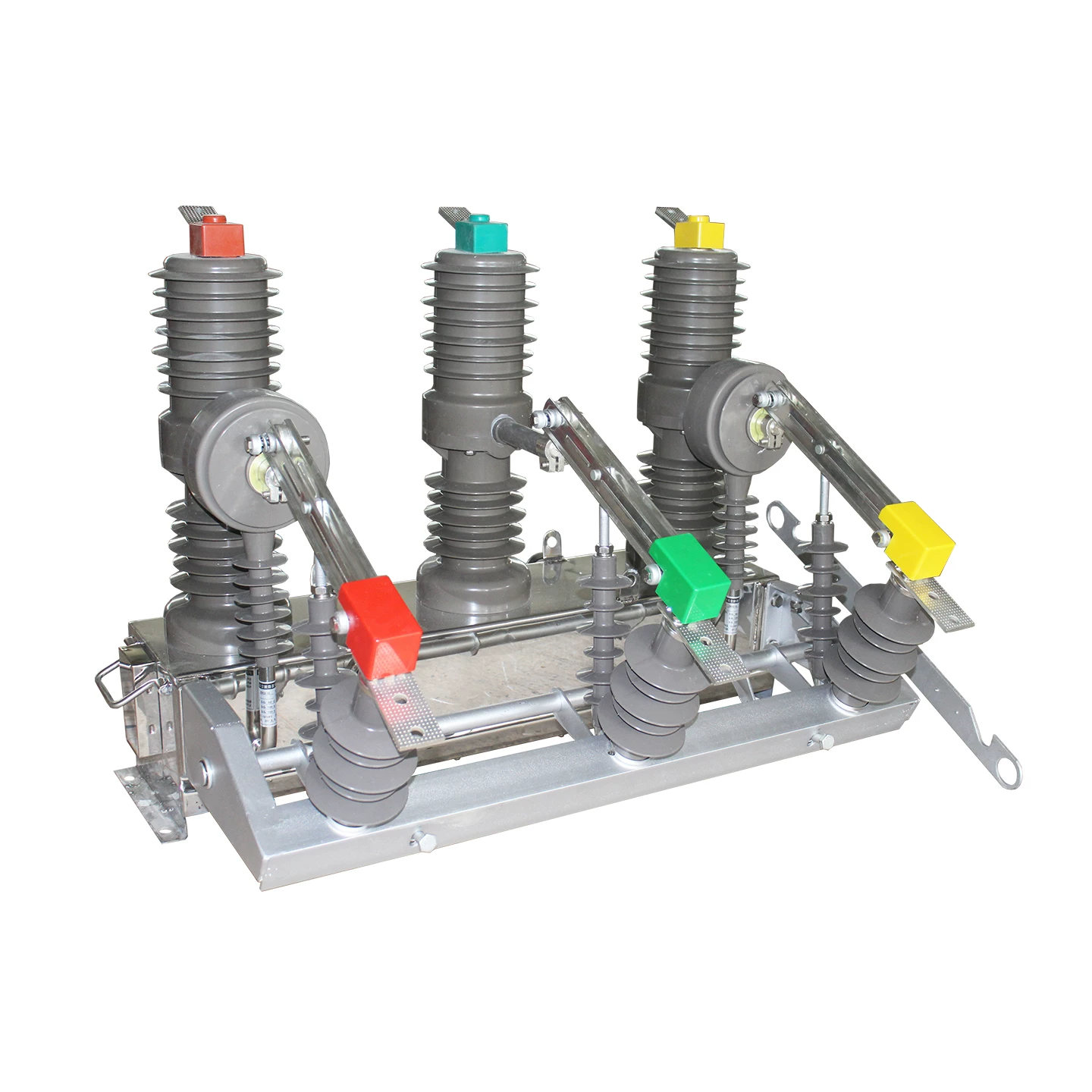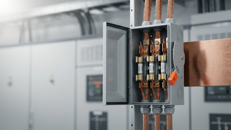
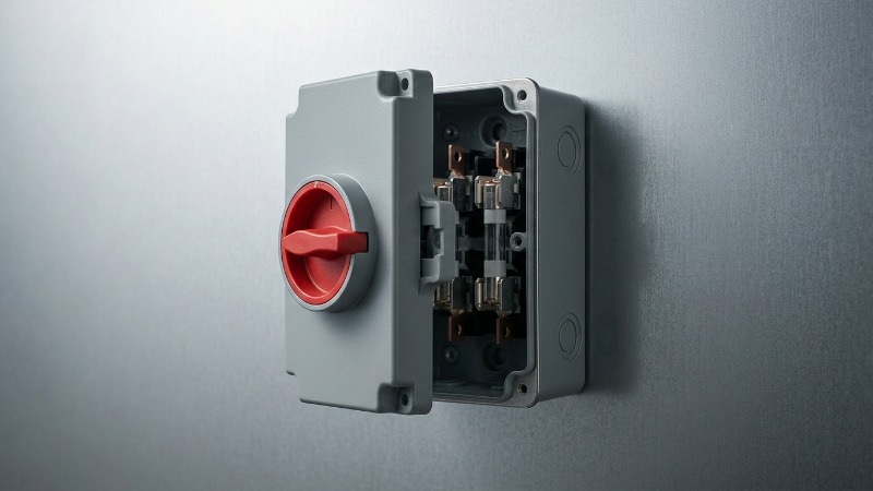
Walk into any well-designed motor control center, and you will find them tucked between the busbar and the load: compact grey boxes with a handle on the front, a fuse carrier inside, and an interlocked door. Engineers who have commissioned enough industrial plants stop thinking of these devices as commodity hardware. They are, in fact, one of the most elegant compromises in low-voltage distribution — a single enclosure that isolates, switches under load, and interrupts fault currents that would vaporize a lesser device.
This guide is written for the working specifier: the panel designer sizing an OEM enclosure to UL 508A, the plant electrical engineer selecting feeder protection, the solar EPC choosing DC combiner hardware. We will move from first principles through construction, standards, sizing, and field practice — with the numbers, tables, and trade-offs that matter when a drawing is due Friday.
1. Fused Disconnect Switch Fundamentals
1.1 Definition and Core Function
A fused disconnect switch is a combined switching-and-protection device that performs three distinct functions inside one enclosure: visible isolation for safe maintenance, on-load switching to make and break rated operating current, and overcurrent and short-circuit protection through integrated fuse links. In IEC terminology, it is called a fuse switch disconnector; in North American practice it is often labeled a fusible safety switch or fused load break switch.
The distinguishing feature is that these three functions are electrically and mechanically coupled. The blades that break the circuit are the same blades that, together with the fuse carrier, form the current path. When the handle is thrown, an operator sees a physical air gap; when a bolted fault occurs, the fuse operates in milliseconds and clamps let-through energy long before the switch contacts would have to interrupt full prospective current.
1.2 Fused vs. Non-Fused Disconnects
A non-fused safety switch is simply a disconnecting means. It can isolate and, if rated, break load current — but it cannot clear a short circuit. Add fuses and the classification changes fundamentally. Under IEC 60947-3, the combination becomes a fuse-combination unit, and its short-circuit performance is defined by the rated conditional short-circuit current — the fault the assembly survives when protected by the specified fuse.
In practical terms, that means a 200 A non-fused disconnect might have an interrupt rating of only 10 kA when tested standalone, while the same frame equipped with a Class J current-limiting fuse can be rated for 200 kA. That is the value proposition in one sentence.
1.3 Where It Fits in the Power Distribution Chain
The fused disconnect typically sits at the boundary between an upstream distribution source — a transformer secondary, main switchboard, or panelboard — and a downstream load: a motor branch circuit, a feeder to a subpanel, a rooftop HVAC unit, or an inverter. It rarely replaces the main circuit breaker; instead it complements it, providing local isolation with fast fault clearing at the load end of the run.
1.3.1 Utilization Categories (AC-21, AC-22, AC-23)
IEC 60947-3 defines utilization categories that tell the specifier what switching duty the device is designed for. Getting this wrong is one of the most common causes of premature failure in the field.
AC-20: Connection and disconnection without load. Isolation only.
AC-21: Switching of resistive loads, including moderate overloads. Lighting circuits and heater banks.
AC-22: Switching of mixed resistive and inductive loads, including moderate overloads. General distribution feeders.
AC-23: Switching of motor loads or other highly inductive loads. Motor branch disconnects require this rating.
An AC-21 device applied to a large motor circuit will weld its contacts within a few years of duty cycling. Always specify AC-23 for motor and transformer feeders, even when the continuous current is well within the frame rating.
2. Anatomy of a Fused Disconnect Switch
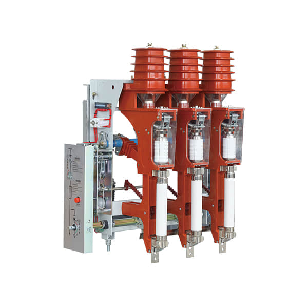
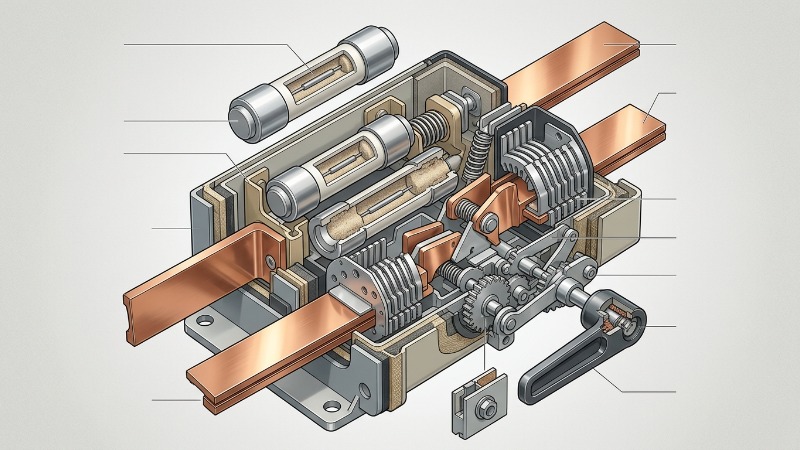
2.1 Main Structural Components
| Component | Function | Typical Material |
|---|---|---|
| Switch blades and contacts | Make and break load current | Silver-plated copper |
| Fuse carriers | Hold and connect fuse links | Glass-reinforced polyester |
| Operating mechanism | Quick-make, quick-break action | Spring-loaded steel |
| Arc chutes | Extinguish arcs during interruption | Ceramic or thermoset composite |
| Enclosure | NEMA 1/3R/4X or IP54/IP65 rated | Steel, stainless, polycarbonate |
| Interlock system | Prevents door opening when energized | Mechanical or electromechanical |
| Auxiliary contacts | Signal switch position to control system | Silver alloy on molded base |
2.2 Fuse Types Used
2.2.1 gG / gL General-Purpose Fuses
These are full-range breaking fuses under IEC 60269-2, meaning they will clear any current from the minimum melting value up to the maximum breaking capacity. They are the default choice for cable protection, general distribution circuits, and non-motor loads. A gG fuse has a well-defined time-current curve that permits close coordination with downstream MCBs and RCBOs.
2.2.2 aM Motor-Rated Fuses
Motor-rated fuses are backup fuses. They ignore overload currents entirely — that job is delegated to the motor overload relay — and only respond to short-circuit currents. This lets the specifier use a smaller fuse ampere rating without nuisance operation during motor starting, where locked-rotor currents can reach 6 to 8 times full-load amps for several seconds.
2.2.3 Class J, R, T, and CC (North American)
| Class | Voltage Rating | Interrupt Rating | Typical Application |
|---|---|---|---|
| Class J | 600 V AC | 200 kA | Feeders, motor branch circuits, control panels |
| Class RK1 | 250 / 600 V AC | 200 kA | General purpose, retrofit for older Class H |
| Class T | 300 / 600 V AC | 200 kA | Compact meter mains, service entrance |
| Class CC | 600 V AC | 200 kA | Control transformers, small motors up to 30 A |
| Class L | 600 V AC | 200 kA | Large feeders 601–6000 A |
2.3 The Quick-Make/Quick-Break Mechanism
Every reputable fuse switch disconnector uses a spring-loaded, energy-storing mechanism to drive the contacts. The handle charges the spring; at a defined threshold, the spring releases and drives the contacts open — or closed — at a speed that is completely independent of how fast or slow the operator moves the handle.
This detail matters more than it sounds. A slow contact separation into a 400 A load current will draw a sustained arc that erodes the contact surfaces and can flash over to ground. Spring action ensures that arc time is measured in half-cycles regardless of who is operating the switch — the third-shift technician on a rush call gets the same performance as the commissioning engineer.
3. How a Fused Disconnect Switch Operates
3.1 Normal Switching Sequence
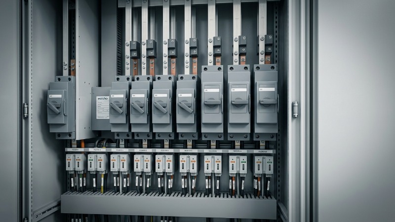
Turning the external handle from OFF to ON energizes the spring-charge mechanism. At the trip point, the springs release the moving contact assembly, which travels rapidly into the fixed contact fingers. Auxiliary contacts change state, signaling position to the PLC or control relay logic. The device is now conducting through the fuse element to the load.
Opening reverses the sequence. The springs drive the contacts apart, arc chutes elongate and cool the resulting arc, and within one to two cycles the current is interrupted. On a properly specified AC-23 unit, this operation can be repeated tens of thousands of times.
3.2 Response to Overcurrent Events
Under a short-circuit condition, the fuse operates first — the switch contacts never see the full fault current. The sequence is worth understanding in detail:
1. Pre-arcing period: The fuse element heats and melts. For a current-limiting fuse under a heavy fault, this can occur in under 5 milliseconds — well before the first current peak.
2. Arcing period: The molten metal vaporizes and forms an arc, which is stretched and cooled by the sand-filled fuse body until circuit voltage can no longer sustain it.
3. Total clearing: The full sequence from fault initiation to zero current, typically under one half-cycle for high fault levels.
The two numbers to know are peak let-through current (Ip) and let-through energy (I²t). A properly selected Class J fuse on a 100 kA prospective fault might limit Ip to under 15 kA and I²t to a few hundred thousand A²s — a fraction of what a molded case breaker would let through before its contacts even begin to part.
3.3 Coordination with Upstream Protection
Selectivity is the discipline of ensuring only the protective device nearest the fault operates. A properly coordinated system leaves the rest of the plant running when a motor terminal box shorts out. With fused disconnects, coordination is usually easier than with breakers because fuse time-current curves are more predictable and repeatable at high fault currents. The rule of thumb: a ratio of at least 1.6:1 between upstream and downstream fuse ratings usually achieves full selectivity, but always verify against manufacturer coordination tables.
4. Key Technical Ratings and Specifications
4.1 Voltage and Current Ratings
The nameplate carries several voltage values that are not interchangeable:
Rated operational voltage (Ue): The voltage at which the switching duty is defined. For a 690 V AC-23 rating, Ue = 690 V.
Rated insulation voltage (Ui): The dielectric withstand reference for creepage and clearance design.
Rated impulse withstand voltage (Uimp): Typically 6 kV or 8 kV for LV distribution, reflecting overvoltage category III or IV.
Rated current (In): Continuous current the device carries at reference ambient without exceeding permitted temperature rise.
4.2 Short-Circuit Withstand and Breaking Capacity
4.2.1 Rated Conditional Short-Circuit Current (Icc)
This is the prospective symmetrical fault current the fuse-switch combination can safely handle when protected by the manufacturer-specified fuse. It is conditional because the number depends entirely on which fuse is installed. A 250 A frame might carry an Icc of 120 kA with a Class J current-limiting fuse and only 50 kA with a slower gG general-purpose fuse.
4.2.2 SCCR in North American Applications
UL 508A requires industrial control panels to be marked with a short-circuit current rating (SCCR). Series-rated combinations — where a specific fuse ahead of a specific device establishes a tested SCCR value — are documented in manufacturer bulletins and referenced during the panel build. For OEMs supplying to specifications requiring 65 kA or 100 kA SCCR, fused disconnects paired with Class J or RK1 fuses are frequently the most economical path.
4.3 Comparative Specification Table
| Parameter | Typical LV Range | Standard Reference |
|---|---|---|
| Rated voltage | 240 V – 690 V AC | IEC 60947-3 |
| Rated current | 16 A – 1600 A | IEC 60947-3 |
| Icc (with specified fuse) | Up to 120 kA | IEC 60947-3 |
| Mechanical endurance | 8,000 – 20,000 cycles | IEC 60947-3 |
| Electrical endurance (AC-23) | 1,000 – 3,000 cycles | IEC 60947-3 |
| Ambient operating temperature | -25 °C to +55 °C | IEC 60947-1 |
| Degree of protection | IP2X to IP65 | IEC 60529 |
| Pollution degree | 3 (industrial) | IEC 60947-1 |
5. Applications Across Industries
5.1 Industrial Motor Circuits
In NEC jurisdictions, Article 430.109 requires a disconnecting means for every motor. A fused disconnect meeting the Type E or Type F combination motor controller definition can serve as motor branch-circuit protection, short-circuit protection, and disconnecting means in a single assembly. On a 75 HP, 480 V motor drawing 96 A full-load, a 200 A fusible disconnect with 175 A Class J time-delay fuses is a typical specification — the fuse tolerates starting inrush while providing short-circuit protection at up to 200 kA.
5.2 Commercial Building Distribution
Feeder isolation in switchboards, service entrance disconnects rated for use as service equipment under NEC 230.66, and rooftop HVAC disconnects rated NEMA 3R for weather exposure are all common commercial applications. The rooftop HVAC application is particularly well-suited to the fused disconnect: the device provides the code-required disconnect within sight of the equipment and the protection required by the nameplate maximum overcurrent device rating.
5.3 Renewable Energy Systems
5.3.1 Solar PV DC-Side Isolation
DC-rated fused disconnects in string combiner boxes handle the unique challenges of DC arcing: no natural current zero and sustained arc energy. IEC 60947-3 Annex D defines DC utilization categories (DC-20 through DC-23) and their associated time constants. For 1000 VDC and 1500 VDC PV plants, purpose-designed DC disconnects with elongated arc chutes and DC-rated PV fuses (gPV class per IEC 60269-6) are mandatory. Using an AC-rated device on DC will result in a fire, not a nuisance trip.
5.3.2 Wind Turbine Nacelle and Battery Storage
In battery energy storage systems (BESS), the extremely low internal impedance of large lithium-ion strings produces prospective fault currents that can exceed 50 kA at rack level. Current-limiting fuses are essential because they cap I²t below the thermal runaway threshold of adjacent cells. A slow-acting breaker in the same application would let through enough energy to propagate a cascade failure through the module.
5.4 Data Center and Critical Power
Downstream PDU and busway tap-off applications leverage the current-limiting behavior of fused disconnects to reduce arc-flash incident energy. As IEEE 1584-2018 arc-flash calculations have become universally applied across critical facilities, retrofitting current-limiting fuses on existing feeders is one of the fastest paths to reducing category 3 or 4 PPE requirements to category 1 or 2 for maintenance staff. Site studies conducted across large colocation portfolios over the past two years consistently show incident energy reductions of 60 to 80 percent when fusible protection replaces older non-current-limiting breakers on 480 V feeders.
5.5 Utility and Transformer Secondary Protection
On the LV side of pad-mount and dry-type transformers, a fused disconnect provides the required secondary protection under NEC 450.3(B) while giving the utility a visible break for maintenance. Specification typically calls for a switch rated at 125% of the transformer secondary FLA with Class L fuses on frames above 600 A.
6. Standards, Codes, and Compliance
6.1 IEC Framework
IEC 60947-3 is the governing standard for switches, disconnectors, switch-disconnectors, and fuse-combination units. Harmonized as EN 60947-3 in Europe, it defines utilization categories, endurance requirements, and conditional short-circuit ratings. The 2020 edition tightened requirements around DC applications and added specific guidance for PV disconnects.
6.2 UL and North American Standards
Four standards define the North American compliance picture:
UL 98: Enclosed and dead-front switches, the fundamental listing for a fused safety switch.
UL 4248 series: Requirements for individual fuseholders by fuse class.
UL 248 series: Low-voltage fuse construction and performance.
NEC Articles 240, 404, 430: Application rules for overcurrent protection, switches, and motor circuits respectively.
6.3 Regional Certifications
For products deployed across global projects, CCC marking is mandatory for China market entry, CE indicates conformity with EU directives (Low Voltage Directive 2014/35/EU chief among them), CSA covers Canada, and KEMA or ASTA type-test reports carry weight with utility and heavy-industry specifiers who demand independent verification of nameplate ratings.
6.4 Arc-Flash and Personnel Safety
NFPA 70E establishes the framework for electrical safety in the workplace, and IEEE 1584 provides the calculation methodology for incident energy. Current-limiting fuses are the single most effective retrofit for reducing arc-flash exposure on existing systems because they cut off fault current before it reaches peak — which is exactly the parameter that drives incident energy in the IEEE 1584-2018 equations.
7. Fused Disconnect Switch vs. Alternative Devices
7.1 Comparison Matrix
| Feature | Fused Disconnect Switch | Molded Case Circuit Breaker | Non-Fused Safety Switch | Load Break Switch |
|---|---|---|---|---|
| Isolation function | Yes (visible break) | Limited (unless SD rated) | Yes | Yes |
| Overcurrent protection | Yes (via fuse) | Yes (built-in) | No | No |
| Short-circuit interrupting | Very high (100–200 kA) | 10–65 kA typical | None | None |
| Resettable after fault | No (replace fuse) | Yes | N/A | N/A |
| Let-through energy | Very low (current-limiting) | Moderate to high | N/A | N/A |
| Selectivity behavior | Excellent, predictable | Requires zone coordination | N/A | Depends |
| Cost per amp (400 A+) | Lower | Higher | Lowest | Low |
| Maintenance | Fuse replacement | Periodic testing | Minimal | Minimal |
7.2 Total Cost of Ownership Analysis
Consider a 400 A industrial feeder over a 20-year lifecycle. A fused disconnect solution typically has 30 to 45 percent lower initial cost than an equivalent MCCB solution at this frame size, offset by fuse replacement following any operation. In a facility with well-coordinated protection, fuse operations are rare events — most industrial audits find fewer than one operation per feeder per decade. Even with three fuse replacements at roughly USD 400 per set of three, the fusible solution retains a lifecycle cost advantage on frames above 250 A.
The MCCB solution wins when frequent operations are expected (test equipment, temporary connections) or when the load includes sensitive electronics that benefit from adjustable trip settings. Above 800 A, the calculus shifts back toward fuses as breaker prices scale non-linearly.
7.3 When Fused Disconnects Win
Choose a fused disconnect when the design brief includes any of: prospective fault currents above 65 kA, arc-flash incident energy reduction targets, single-shot reliability requirements, tight coordination with downstream fuses, or high-ambient environments where breaker thermal trip curves become unreliable. Choose an MCCB when the priority is remote operation, adjustable trip characteristics, or resettability after nuisance operations.
8. Selection and Sizing Guide
8.1 Load Analysis Checklist
Continuous load current and duty cycle profile
Inrush characteristics — motor starting, transformer magnetizing, capacitor bank switching
Ambient temperature at the installation location, with derating factors applied
Altitude correction for installations above 2,000 m (roughly 0.5% capacity reduction per 100 m)
Harmonic content — non-linear loads may require oversized neutral conductors and fuse ratings
Available short-circuit current at the point of installation
8.2 Fuse Selection Methodology
8.2.1 Time-Current Curve Coordination
Overlay the TCC of the fuse against upstream and downstream protective devices on a log-log plot. The downstream curve must lie entirely below and to the left of the upstream curve at every current value the system can experience. Where the curves cross, selectivity is lost — the upstream device may trip before or simultaneously with the downstream device. For fuses in series, a rule of thumb ratio of 1.6:1 between ratings usually achieves full selectivity, but this must always be verified against manufacturer coordination tables.
8.2.2 I²t Coordination
At high fault currents, TCC curves become vertical lines and lose usefulness. Coordinate instead by comparing the total clearing I²t of the downstream fuse to the pre-arcing (minimum melting) I²t of the upstream fuse. If total clearing I²t of the downstream device is less than the pre-arcing I²t of the upstream device, the downstream fuse will clear the fault before the upstream fuse element even begins to melt.
8.3 Enclosure Selection
| Environment | NEMA Rating | IP Equivalent |
|---|---|---|
| Indoor, clean, dry | NEMA 1 | IP30 |
| Outdoor, rain and sleet | NEMA 3R | IP24 |
| Washdown, food processing | NEMA 4X | IP66 |
| Corrosive chemical | NEMA 4X stainless | IP66 |
| Hazardous, gas atmosphere | Class I Div 2 or ATEX Zone 2 | Depends on certification |
8.4 Sample Sizing Table for Motor Circuits
| Motor Size (HP @ 480 V) | FLA (A) | Recommended Switch Rating | Class J Time-Delay Fuse |
|---|---|---|---|
| 10 | 14 | 30 A | 25 A |
| 25 | 34 | 60 A | 60 A |
| 50 | 65 | 100 A | 110 A |
| 100 | 124 | 200 A | 200 A |
| 200 | 240 | 400 A | 400 A |
Values illustrative and based on NEC 430.52 maximum ratings for Class J time-delay fuses at 175% of FLA. Always verify against manufacturer coordination charts and the specific motor nameplate.
9. Installation, Commissioning, and Maintenance
9.1 Installation Best Practices
Every terminal connection is a potential failure point. Torque cable lugs to the manufacturer's specification — typically stamped inside the enclosure door — using a calibrated torque wrench, not a ratcheting screwdriver by feel. Verify phase rotation before energization on any three-phase circuit feeding a motor. Confirm grounding continuity from the enclosure to the equipment ground bar with a low-resistance ohmmeter, not a general-purpose DMM.
For compression lugs, use the die specified by the lug manufacturer. Mechanical lugs must accept the conductor size range on their nameplate — undersizing forces the strand pattern to compress unevenly and creates hot spots that will show up on the first thermographic survey.
9.2 Commissioning Tests
Before energization, perform:
Insulation resistance per IEEE 43 — phase to phase and phase to ground, with results recorded for baseline comparison.
Contact resistance measurement using a micro-ohmmeter, comparing pole-to-pole and against manufacturer maximums.
Operational cycling — at least five no-load open-close cycles to verify mechanism smoothness.
Auxiliary contact verification — ring out to the control system and confirm correct state indication.
9.3 Preventive Maintenance Schedule
| Interval | Activity |
|---|---|
| Every 12 months | Visual inspection, thermographic scan under normal load |
| Every 3 years | De-energized inspection, contact wear check, torque verification |
| Every 5 years | Contact resistance measurement, insulation resistance test |
| After any fault clearance | Full inspection, fuse replacement with matching class, voltage, and interrupting rating |
9.4 Common Failure Modes
Overheated fuse clips from loss of spring pressure. Thermography will find this first; touch will find it only after damage has occurred.
Fuse mis-replacement — wrong class, wrong voltage, wrong interrupting rating. The most common cause is a maintenance electrician grabbing whatever fits.
Moisture ingress in outdoor enclosures where conduit hubs were installed without proper sealant.
Mechanism binding after long dormant periods, particularly in coastal or high-humidity installations where lubricant migrates or oxidizes.
9.5 Lockout/Tagout Procedures
OSHA 29 CFR 1910.147 defines the minimum requirements for LOTO. For a fused disconnect: open the switch, apply the personal padlock through the handle hasp, tag the device, and verify zero voltage on all phases and to ground using a properly rated test instrument (Category III or IV depending on the location). Then perform a live-dead-live test on the meter itself before and after the verification measurement. Only then is the circuit safe to work.
10. Market Trends and Emerging Technology
10.1 Smart and Connected Fused Disconnects
Integration of thermal sensors, current monitoring, and IoT gateways is transforming what has historically been a purely electromechanical product. Recent industry analyses place the smart LV switching segment growth at 8 to 10 percent CAGR, driven by data center and industrial automation demand. The value proposition is predictive maintenance: a fuse clip trending 15 °C above baseline over six weeks is a scheduled repair, not an unplanned outage.
10.2 DC Ratings for Electrification
EV fast-charging infrastructure, battery storage, and 1500 VDC solar plants have driven substantial expansion of DC-rated fused disconnect offerings. The technical challenge is real: DC arcs do not self-extinguish at current zero, so DC-rated devices need magnetic blow-out coils, elongated arc chutes, and specific polarity configurations. The premium over AC-equivalent devices reflects this — typically 40 to 70 percent — but there is no substitute.
10.3 Arc-Flash Mitigation Advances
Current-limiting fuses combined with optical arc sensors are increasingly deployed as an alternative to arc-resistant switchgear retrofits. Where an arc-resistant lineup might cost several times the base switchgear price, adding current-limiting protection and light-sensing trip logic can achieve comparable incident energy reduction at a fraction of the capital outlay.
10.4 Sustainability and Materials
The move toward SF6-free designs in medium-voltage disconnects is trickling into LV specifications through customer sustainability mandates. RoHS compliance for fuse construction, halogen-free enclosure polymers, and end-of-life recyclability are increasingly written into tender documents from EU utilities and multinational manufacturers.
11. Frequently Asked Questions
Can I replace a blown fuse with a higher-rated one to prevent recurrence?
No. The fuse rating is coordinated with the switch's rated conditional short-circuit current, the conductor ampacity, and the downstream equipment protection scheme. Upsizing defeats current limitation, invalidates the SCCR of the assembly, voids code compliance under NEC 240.4, and may violate the switch listing entirely. If a fuse operates repeatedly, the correct response is to investigate the load — not to upsize the protection.
Is a fused disconnect switch the same as a fuse box?
No. A residential fuse box is a distribution panel with individual fuses protecting each branch circuit. A fused disconnect switch is a single combined switching-and-protection device typically used at feeder or equipment level, with one set of fuses protecting the load it serves. The mechanisms, ratings, and applications are fundamentally different.
What is the difference between a fuse switch disconnector and a switch fuse?
The distinction lies in the physical arrangement inside the enclosure. A switch-fuse has the switching contacts upstream of the fuse; opening the switch de-energizes the fuse. A fuse-switch or fuse switch disconnector incorporates the fuse into the moving contact assembly itself — the fuse carrier is the switch. IEC 60947-3 defines each construction precisely, and the operational implications for maintenance and fault behavior differ.
Can fused disconnect switches be used as service entrance equipment?
Yes, provided the device is specifically listed and labeled as "Suitable for Use as Service Equipment" under UL 98 and installed in accordance with NEC Article 230. Service entrance duty imposes additional requirements around bonding, neutral connection, and available fault current.
How do I know if my fuse is current-limiting?
Check the fuse class marking and consult the manufacturer's published peak let-through (Ip) and I²t data. In North America, Class J, T, RK1, CC, and L fuses are current-limiting. Under IEC 60269, gG and aM fuses with the "current-limiting" designation on their nameplate qualify. If the data sheet does not publish peak let-through curves, the fuse is almost certainly not current-limiting.
What is the expected service life?
Mechanical life for a quality fused disconnect switch is typically 8,000 to 20,000 no-load operations. Electrical life at rated current and utilization category ranges from 1,000 to 3,000 operations. In typical industrial service with a few operations per year, the mechanical life expectancy well exceeds a 30-year installation lifespan.
Are fused disconnects suitable for DC solar applications?
Only devices specifically DC-rated for the system voltage, polarity, and installation configuration. An AC-rated switch installed on DC will fail catastrophically the first time it is opened under load because the arc will not self-extinguish. Use only products carrying explicit DC ratings and gPV-class fuses rated for the string voltage.
12. Key Takeaways and Next Steps
12.1 Summary of Engineering Considerations
Every specification decision comes down to five parameters: voltage class (matched to system Ue with adequate margin), current rating (sized for continuous load with derating), fuse type and class (matched to load characteristics and coordination requirements), enclosure (matched to environment), and coordination (verified with upstream and downstream protection curves and I²t data).
Get those five right, and the device will do exactly what it is supposed to do — including the one thing you hope it never has to do.
12.2 Specification Checklist
Build a standardized specification template covering: rated voltage and current, utilization category, Icc with specified fuse, fuse class and ampere rating, enclosure NEMA/IP rating, auxiliary contact requirements, mounting orientation, terminal type, and applicable listings (UL 98, IEC 60947-3, CCC, CE). Circulate this template internally so every project starts from the same baseline.
12.3 Partner with a Specialist: Weisho Electric
The technical depth in this guide reflects a truth that seasoned specifiers already know: a fused disconnect switch is only as good as the engineering behind it. Manufacturing tolerances on contact geometry, spring metallurgy, arc chute design, and terminal plating separate products that meet the datasheet from products that deliver 20 years of reliable service in a demanding environment.
Weisho Electric has built its reputation around exactly this level of engineering rigor. As a specialist manufacturer of low-voltage switching and protection equipment, Weisho supplies fuse switch disconnectors, isolators, and combination units built to IEC 60947-3, UL 98, and CCC standards, with type-test verification for AC-23 duty and conditional short-circuit ratings up to 120 kA. The product range spans 16 A through 1600 A frames, AC and DC configurations, and enclosure options from IP30 indoor to IP65 washdown — with DC-rated versions certified for 1500 VDC PV and BESS applications.
What distinguishes Weisho for OEM panel builders and EPC contractors is not just the product but the technical support behind it: coordination tables published for every frame size, series-rated SCCR documentation available for UL 508A panel builds, DC-side coordination guidance for solar and storage projects, and application engineering that responds in the language of the specifier — with data sheets, TCC curves, and I²t values that a working engineer can drop directly into a coordination study.
For project-specific coordination studies, custom-configured combination units, or bulk-quantity OEM programs, contact Weisho Electric's application engineering team. Request manufacturer coordination tables, UL 508A series-rated combination documentation, and DC application guidance directly from the source. Whether the requirement is a single 100 A rooftop HVAC disconnect or a 1600 A main-tie-main assembly with matched Class L fuses, the Weisho Electric team can turn a specification into a shipped, certified, correctly documented product.
Get in touch with Weisho Electric today to discuss your next low-voltage protection project — and put the engineering rigor described in this guide to work on your drawings, your panels, and your installations.