Section I: Introduction—Defining the CT and Its Core Value Proposition
In the dynamic field of electrical engineering, the acronym CT fundamentally stands for Current Transformer, representing a crucial piece of specialized equipment. Its primary and vital function is to safely and accurately step down the substantial current flowing through a high-voltage AC primary circuit, converting it into a standardized, manageable low current signal (typically 5A or 1A) using the principle of electromagnetic induction.
This scaled-down, isolated signal is then fed to critical low-voltage secondary devices, including energy metering instruments, sophisticated monitoring systems, and essential protective relays. Consequently, the Current Transformer serves as the indispensable "safety bridge" and "information translator" linking the high-power primary circuit with sensitive low-voltage control loops, performing an essential mediating role.
The efficient management and reliable operation of any modern power system are heavily dependent on the unwavering performance of the CT. Whether operating on the main busbars of a massive power generation plant, deep within the transmission network's substations, or integrated into the switchgear of an industrial facility, the CT is the foundational sensor enabling precise billing, automated system monitoring, and rapid fault clearing. By safely isolating high voltages, CTs safeguard personnel working with low-voltage secondary equipment while ensuring that power devices function with high measurement accuracy even in extremely high-current environments.
Key Takeaways: The CT Quick Reference
Here are the essential facts about Current Transformers that every engineer needs to keep top of mind:
— The CT is fundamentally a high-precision, high-isolation current sensor designed to convert massive primary circuit currents into safe, standardized secondary currents for downstream equipment.
— Its function is triple-pronged, revolving around secure electrical isolation, supplying highly accurate signals for revenue metering, and providing the reliable input required for protective relay operation.
— Engineering selection mandates careful consideration of the CT’s intended purpose (protection or metering) to choose the corresponding Accuracy Class (e.g., 0.2S or 5P10), and requires verification that the total Actual Burden of the secondary loop remains safely below the CT’s rated Burden capacity.
— The absolute golden rule of CT operation, which must never be violated, is that the secondary circuit of a Current Transformer must never be operated open-circuited.
— Violating this safety rule results in extremely high, dangerous voltage spikes (potentially thousands of volts), posing a severe risk to both human safety and the connected equipment.
— Practical field experience dictates that the very first step before performing any maintenance, connection, or removal of equipment on the CT's secondary side is to install a reliable short-circuit across its secondary terminals.
Section II: CT Fundamentals—Basic Principles and Structural Anatomy

The Working Principle: Current Step-Down via Electromagnetic Induction
The operational principle of a Current Transformer closely parallels that of a power transformer, with both relying entirely on Faraday's principle of electromagnetic induction. The core functional structure involves closely linking the primary and secondary windings through a common magnetic flux path within the core material.
The Primary Winding (Np) has a very low number of turns, typically ranging from a single turn (a busbar pass-through) to just a few turns, and is directly connected in series with the circuit where the current must be measured. Due to its low impedance, this winding ensures the CT has a negligible impact on the main power circuit during normal operation.
Conversely, the Secondary Winding (Ns) consists of a comparatively larger number of turns and is connected in series with the current coils of the measurement instruments or protective relays, delivering the standardized secondary current. When the high primary current flows through the primary winding, it induces a magnetic flux within the iron core; this flux subsequently induces an electromotive force (EMF) across the secondary winding, driving the secondary current through the closed loop.
Crucially, based on the principle of magneto-motive force (MMF) balance (which effectively ignores the minor excitation current), the primary current multiplied by the primary turns is approximately equal to the secondary current multiplied by the secondary turns. By meticulously controlling this specific turns ratio (Np: Ns), the CT achieves a highly precise "step-down" of the current, ensuring the conversion ratio remains highly linear within its standard operating range.
Defining the Current Transformation Ratio (CT Ratio)
The Current Transformation Ratio, denoted as Ki, is the single most fundamental parameter in CT design and application, defined simply as the ratio of the rated primary current to the rated secondary current.
For instance, if a CT's nameplate specifies a ratio of 400/5A, its Current Transformation Ratio (Ki) is 80; this means that when the main circuit current reaches 400A, the secondary circuit is engineered to output a standard 5A current.
Regarding standardization, the rated secondary current has been internationally standardized almost universally to 5A or, in certain applications, 1A. The primary rationale for adopting the 1A standard is the reduction of power loss and voltage drop across the secondary circuit over long cable runs, a feature especially useful in large substations or industrial settings where measuring devices are located significantly far from the CTs.
Structural Comparison: Primary vs. Secondary Side
The table below highlights the crucial differences between the primary and secondary sides from an engineering perspective:
| Characteristic | Primary Side (P1-P2) | Secondary Side (S1-S2) | Engineering Implication |
| Connection Point | High-voltage main circuit or high-current busbar | Low-voltage devices, meters, or protective relays | Facilitates information transfer and secures electrical isolation. |
| Current Level | High (Rated values can reach tens of thousands of Amps) | Low (Standardized at 5A or 1A) | Standardizes the signal for processing by low-voltage control equipment. |
| Voltage Level | High (kV class, same as the main circuit voltage) | Low (Typically < 100V, dependent on burden and impedance) | Essential Safety Isolation, protecting personnel and sensitive instruments. |
| Winding Turns | Extremely few (Often Primary Turns $\le 5$) | Numerous (The turns ratio dictates the current transformation) | Precisely controls the current transformation ratio via the physical winding count. |
| Impedance Profile | Extremely low (Ideally near zero) | Low (Must account for external burden and wire resistance) | Ensures the CT does not introduce a significant voltage drop into the main power circuit. |
Note: While the CT's primary side operates at the same high voltage level as the main circuit, its design is primarily driven by current handling capacity rather than voltage rating; nevertheless, all CT safety protocols are centered on its high current isolation capabilities.
CT Working Principle Animation
To gain a clear and rapid understanding of how a Current Transformer harnesses electromagnetic induction to achieve the safe scaling of high currents into low currents, we recommend viewing the following animated demonstration:
Section III: The Core Functions of a CT—Isolation, Accuracy, and Error Management
Function 1: Secure Electrical Isolation—The Primary Safety Mandate
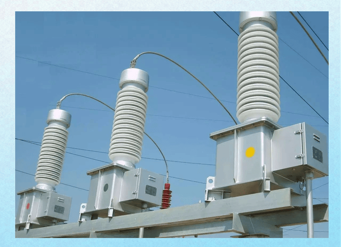
This capability represents the paramount mission of the CT within the architecture of any power system. The CT is meticulously engineered with high-strength insulation separating its primary and secondary windings, which ensures that even when the primary circuit is energized at hundreds of kilovolts, the secondary circuit remains at a safe, low potential relative to the ground.
This crucial isolation is achieved through robust physical insulating materials, which may include epoxy resin, porcelain casings, or specialized insulating oil. This high level of insulation dramatically mitigates the risk of high-voltage shock to personnel—whether they are involved in operation, maintenance, or simple metering tasks.
Function 2: Delivering Precise Signals for Revenue Metering
To uphold the integrity and fairness of energy transactions, metering-class CTs must be capable of maintaining an extremely high level of accuracy across wide temperature fluctuations, varied operating conditions, and extended periods of time. These CTs (such as the 0.2S class) demand specialized core materials and designs that ensure their magnetic characteristics remain highly linear, resulting in minimal excitation current. This strict adherence to linearity is necessary to minimize both the ratio error and the phase angle error.
Metering applications, whether for commercial billing or internal energy auditing, rely completely on these highly accurate CT outputs. The signals are utilized by energy meters, power quality analyzers, and advanced digital multimeters to precisely measure key parameters like active power, reactive power, apparent power, and power factor.
Function 3: Enabling Protection and Control—The Fault Sentinel
Protective relaying systems function as the final, non-negotiable line of defense for a power system, and protection-class CTs are required to supply a prompt and precise signal during fault conditions. When severe events such as a short circuit or heavy overload occur, the current can instantaneously surge to twenty times its rated value or more. The protection CT is specifically designed to maintain the integrity and fidelity of this signal throughout this massive instantaneous transient process, thereby guaranteeing that the protective relay can execute a rapid, accurate decision and issue the essential trip command.
The output signals from CTs are the foundational inputs for a wide array of complex protective logics, including overcurrent protection, ground fault detection, transformer differential protection, and busbar zone protection.
Engineering Focus: Ratio and Phase Errors—The Hidden Challenges to Accuracy
In an ideal, theoretical scenario, a CT's transformation ratio would be perfect, with the secondary current's phase being perfectly 180 degrees opposite the primary current. However, in the real world, errors inevitably arise due to the minor excitation current required to establish magnetic flux in the core, along with the existence of leakage flux and winding resistance.
— Ratio Error (Delta I): This quantifiable error reflects the percentage deviation between the actual transformation ratio and the theoretical ideal ratio. The magnitude of this ratio error is directly responsible for the inaccuracies observed in the measured electrical energy value.
— Phase Angle Error (Delta): This error represents the angular deviation, or phase shift, of the secondary current vector relative to the inverted primary current vector. This subtle phase deviation becomes absolutely critical and must be carefully controlled, especially when making accurate measurements of reactive power and power factor.
To counter these effects, high-quality CTs, particularly those designed for high-precision metering, utilize optimized core materials and structural designs (such as permalloy or amorphous alloys) to rigorously minimize these errors, particularly for S-Class CTs, which are uniquely required to maintain their strict error limits even under low-current operating conditions.
Tip: It is essential to remember that the accuracy requirement for Metering-Class CTs is focused exclusively on the normal operating current range, while the accuracy requirement for Protection-Class CTs is focused on the reliability of the signal within the high-magnitude fault current range. Understanding this fundamental distinction is the key to correct CT selection.

Section IV: CT Applications and Specialized Configurations
Application 1: Commercial and Industrial Energy Metering
CTs are non-negotiable components at all points where energy consumption must be measured for financial transactions or billing purposes. These commercial applications typically require the use of high-accuracy classes, such as 0.2S or 0.5S, to ensure impeccable billing fairness and regulatory compliance.
Beyond revenue transactions, CTs are extensively used for internal energy auditing and monitoring within large facilities and industrial plants. They enable facility managers to conduct detailed energy efficiency analyses and perform optimization based on accurate load profiles.
Application 2: Large-Scale Power System Protection
In high-voltage environments, CTs supply the critical current data necessary for advanced, complex protection functions within costly core assets such as transformers, generators, and busbars. They are fundamental to sophisticated systems like differential protection and winding temperature monitoring.
For transmission and distribution systems, CTs provide the essential current signals used by protective relays to implement immediate overcurrent and short-circuit protection. This capability ensures that electrical faults are rapidly detected and isolated, preventing widespread damage across the grid.
Application 3: Niche and Advanced Applications
CT signals are used to monitor current in complex circuits like capacitor banks and shunt reactors. This monitoring provides crucial input to automatic power factor correction equipment and internal fault protection relays, thereby ensuring the voltage stability and proper power factor management of the electrical network.
Although this article primarily discusses AC CTs, specialized DC CTs based on principles like the Hall effect are increasingly vital in modern power systems. Their use is expanding rapidly across emerging sectors such as solar PV generation, battery energy storage, and high-voltage direct current (HVDC) transmission.
The Grounding Guard: Zero-Sequence Current Transformers (ZCTs)
The Zero-Sequence Current Transformer (ZCT) represents a specialized application of the CT principle, featuring a unique structural design. In this configuration, all three phase conductors (A, B, and C) and often the neutral conductor (N) pass collectively through a single toroidal iron core opening.
The principle relies on Kirchhoff's Current Law: under normal operating conditions or during balanced phase-to-phase short circuits, the vector sum of the currents flowing through the three phases is theoretically zero, resulting in zero induced current on the ZCT's secondary side. However, if a single-phase-to-ground fault occurs, the resulting fault current completes its path through the earth, causing the three-phase current vector sum to become non-zero; this non-zero residual current is known as the zero-sequence current.
The ZCT is highly sensitive and precisely designed to detect this minimal zero-sequence current. It then transmits the signal to a specialized ground fault protection relay, enabling rapid and highly reliable single-phase-to-ground fault protection. In systems where grounding is not directly tied to the earth or in medium-to-low voltage distribution networks, the ZCT is an indispensable component for detecting dangerous earth faults that could otherwise be missed by standard phase protection schemes.
Section V: CT Types, Performance Differences, and Selection Criteria
For every electrical engineer, correctly selecting the appropriate CT is a prerequisite for ensuring both the safety and the accurate operation of the power system. Selection decisions must extend well beyond the simple turns ratio to focus intensely on the Accuracy Class and the Secondary Burden requirements.
Classification and Key Differentiation of CT Types
| CT Type | Structural Features | Typical Application | Unique Engineering Advantage |
| Wound Type | The primary winding has multiple turns, connected in series with the main circuit. | Small distribution panels, laboratory testing, and extremely high-precision metering applications. | Structure is similar to a conventional transformer, allowing for the achievement of the absolute highest accuracy classes. |
| Bar / Toroidal Type | The primary winding is simply the main busbar or cable passing directly through the CT core aperture. | Widely used in switchgear, circuit breaker compartments, and across most high-voltage circuits. | Extremely robust and highly resistant to severe short-circuit currents, offering maximum installation simplicity. |
| Clamp-on Type | Features an openable core structure, allowing for attachment without interrupting the primary circuit power. | Primarily used for field maintenance and temporary current measurement, and troubleshooting. | Eliminates the need to de-energize the main circuit for measurement, providing immense flexibility and safety during maintenance. |
| Electronic / LPIT | Based on principles like Rogowski coils or fiber optics, these typically have no magnetic core. | Digital substations and Ultra-High Voltage (UHV) applications in advanced grids. | Eliminates core saturation issues, offers a massive dynamic range, is compact, and critically, presents no secondary open-circuit danger, marking it as the technology of the future. |
Selection Criterion 1: Accuracy Class—Metering vs. Protection
The Accuracy Class is the determinant of the CT's intended application and its performance standard.
Metering Class (e.g., 0.2, 0.5, 0.2S):
Objective: The goal is to strictly maintain the total error within a minute percentage (e.g., 0.2%) across the normal operating range, which can span from 1% up to 120% of the rated current for S-Class CTs.
Design Priority: The core is engineered to operate far from the saturation knee point within the working range, minimizing the excitation current to guarantee maximum precision.
Protection Class (e.g., 5P10, 10P20):
Objective: The objective is to ensure that the composite error remains below a specified percentage (e.g., 5% or 10%) when the current reaches the Rated Accuracy Limit Current (RALC), which is typically 5 to 20 times the nominal rated current. This guarantees the protective relay operates reliably during a major fault.
Design Priority: The core is designed to maximize its ability to resist saturation under extreme high-fault currents, prioritizing fault response reliability over fine-grained accuracy at normal loads.
Note: The Accuracy Limit Factor (ALF) of a protection CT, for example the '10' in 5P10, specifies that the CT must maintain its error requirement (5P or 10P) even when exposed to a fault current that is 10 times the nominal rated primary current. This factor is the most critical metric for assessing the CT's saturation resistance.
Selection Criterion 2: Rated Secondary Burden (Burden)
— Definition: The Rated Secondary Burden, SN, is the maximum apparent power (measured in VA) that the CT's secondary winding is designed to accommodate in the external circuit while flowing its rated secondary current.
— Composition: The necessary Rated Secondary Burden must always be greater than or equal to the total power consumption (Actual Burden) of all connected devices (meter coils, relay coils) plus the impedance losses from all connecting wires in the secondary loop.
— Importance:
Over-Burdening (Actual Burden > Rated Burden): This situation causes the CT core to prematurely saturate, leading to severe distortion and harmonic corruption of the secondary current signal. This results in metering inaccuracies and, more critically, may cause the protective relay to fail to operate (nuisance trip or protection failure).
Under-Burdening (Actual Burden < 25% of Rated Burden): While safe, extremely light loading can slightly increase the CT's inherent error at low current levels.
— Selection Principle: When designing the secondary circuit, the engineer must precisely calculate the total load and impedance, then select a CT whose Rated Burden is slightly higher than the calculated Actual Burden.

Section VI: The CT Safety Mandate—The Secondary Open-Circuit Hazard
In all operational and maintenance procedures related to Current Transformers, one rule stands as the absolute foundation—it is universally known as the "Golden Rule of CT Operation": The secondary terminals of a Current Transformer must never be operated open-circuited under any circumstances whatsoever!
1. The Fatal Physics of Secondary Open Circuits
When a CT is operating normally, the secondary side forms a closed, low-impedance circuit, and the current flowing in the secondary winding generates a counter-magnetic flux that almost perfectly cancels the flux generated by the primary current. This maintains the net magnetic flux within the iron core at a manageable, low-level state.
However, the moment the secondary loop is unexpectedly opened (e.g., a loose terminal connection, removal of a meter), the physics change drastically:
— MMF Balance is Lost: The secondary current instantaneously drops to zero, eliminating the necessary counter-flux.
— Excitation Current Surges: The entire magnetomotive force of the primary current is then devoted to establishing flux in the core. The magnetic flux density within the core rapidly and uncontrollably increases, driving the core into deep saturation.
— Lethal Voltage Generation: According to Faraday’s Law, the induced electromotive force is directly proportional to the number of secondary turns and the rate of change of the magnetic flux. As the deeply saturated iron core experiences extreme, non-sinusoidal flux spikes, the secondary winding induces lethal peak voltages that can reach thousands or even tens of thousands of volts across the open terminals.
2. The Catastrophic Consequences of High Voltage
— Personnel Hazard: The resulting high voltage spike poses an immediate, life-threatening electrocution risk to any personnel or operator near the open terminals.
— Insulation Failure: The massive induced voltage can physically breach the CT's own internal secondary insulation, leading to permanent damage and total failure of the CT unit.
— Equipment Damage: The voltage transient will irrevocably destroy or severely damage all low-voltage precision instruments and relays connected to the secondary side of the CT.
CT Secondary Open-Circuit Danger Demonstration
To provide a more impactful and visual understanding of the principle and severe consequences resulting from a CT secondary open circuit, we recommend reviewing the following segment of the video (we suggest starting the video playback at [00:28:00]):
3. Practical Field Safety and the Golden Rule
— The Golden Rule Mandate: Under absolutely all circumstances, the secondary side of the CT must be maintained as a low-impedance, closed circuit.
— Maintenance Procedure: Before performing any work—including installation, replacement, maintenance, or removal of any equipment on the secondary side—the operator must first utilize dedicated shorting links or a shorting switch to reliably and securely short-circuit the CT's secondary terminals.
— Engineering Design: It is standard practice in panel design to utilize CT-specific terminal blocks that incorporate a built-in shorting feature. This thoughtful design allows maintenance personnel to safely perform the shorting operation in an isolated and controlled manner before the work proceeds.
Tip: If an operator discovers a CT secondary circuit is already open-circuited, their priority—before attempting to shut down the primary power—is to immediately and safely (using insulated tools and gloves) permanently short-circuit the secondary terminals at the earliest point possible. This action is the only viable path to saving the CT from irreversible damage and mitigating the hazard to personnel.
Section VII: Conclusion—The Irreplaceable Role of the CT
The Current Transformer functions as the essential, non-negotiable link connecting the massive world of high-voltage power with the delicate realm of low-voltage control systems. Its fundamental roles in safety isolation, highly accurate metering, and reliable fault protection make it irreplaceable within the electrical infrastructure.
While innovative technologies like the electronic CT (LPIT), represented by devices such as the Rogowski coil, are emerging as preferred solutions for future digital substations and UHV applications due to their high linearity and immunity to saturation, the conventional electromagnetic CT remains dominant. Due to its proven technological maturity, exceptionally high reliability, and lower relative cost, the traditional CT will continue to be deployed and maintain its core value in vast medium- and low-voltage industrial and distribution networks worldwide.
Frequently Asked Questions (FAQ)
Q1: What is the fundamental difference between a CT and a PT (Voltage Transformer), and are they interchangeable?
A: CTs and PTs (Potential Transformers, also known as VTs) are both classified as instrument transformers, but their functionality and connection methods are diametrically opposite; they are absolutely not interchangeable.
CT (Current Transformer): It is connected in series with the main circuit to step high current down to low current. Its secondary side must never be open-circuited.
PT (Potential Transformer): It is connected in parallel with the main circuit to step high voltage down to low voltage. Its secondary side must never be short-circuited (a short circuit would cause the PT to burn out).
These two types serve complementary roles within the power system, collectively supplying the necessary current and voltage signals to all downstream instrumentation and protective relays.
Q2: What defines an S-Class CT (e.g., 0.2S), and what is its advantage over a standard 0.2 Class?
A: The designation 'S' stands for "Special Metering." The primary engineering advantage of a 0.2S class CT is its ability to maintain high accuracy even under extremely low current loads (specifically between 1% and 5% of the rated current). A standard 0.2 class CT typically only guarantees its specified accuracy from 5% or 10% of the rated current upwards. For sites experiencing dramatic "tidal" load profiles—such as commercial buildings with very low current usage during off-peak hours—using a 0.2S class CT ensures that energy consumption is accurately metered around the clock, thereby eliminating significant cumulative metering errors during low-load periods.
Q3: What happens if a screw on the CT secondary terminal block loosens or falls out?
A: A loose screw is one of the most common causes of CT secondary circuit failure in the field. The consequence depends entirely on the degree of connection loss:
— Poor Contact: If the screw is merely loose, it will increase the resistance of the secondary circuit. This effectively increases the Actual Burden, potentially pushing the CT into an over-burdened state, which introduces significant ratio and phase errors, thus compromising metering and protection accuracy.
— Total Disconnection (Most Dangerous): If the screw falls out completely or the contact is fully lost, the CT secondary circuit becomes open-circuited, immediately triggering the dangerous high-voltage condition (potentially thousands of volts), which threatens personnel safety and will likely destroy the connected low-voltage devices.
Action Recommended: The operator's immediate priority, after confirming the primary circuit is either de-energized or the CT secondary side is safely shorted, must be to securely tighten the loose screw to restore the low-impedance circuit path.
Q4: How should an engineer interpret the "5P10" designation on a protection-class CT?
A: The 5P10 label is a standard designation for a protection-class CT, conveying two pieces of critical performance information:
— 5P: This indicates that the Composite Error (the combined current and phase error) must not exceed 5% at the Rated Accuracy Limit Current (P stands for Protection).
— 10: This number represents the Accuracy Limit Factor (ALF), which is 10. This means the CT is guaranteed to maintain its 5% error limit even when subjected to a fault current that is 10 times the nominal rated primary current.
This complete designation is the primary data point engineers use to select a CT that is robust enough to match the protective relay's operating range and the maximum calculated fault current of the power system.
Q5: Why is the CT secondary circuit required to have a single-point ground, rather than multiple grounds or no ground at all?
A: The mandatory single-point grounding is a non-negotiable safety requirement for CT secondary wiring:
— Purpose of Grounding: Grounding the secondary circuit ensures that its voltage is safely clamped to the earth potential, preventing lethal voltage buildup and providing a safe path to ground if the primary side insulation fails and high voltage breaches the barrier.
— No Ground (Incorrect): If the secondary circuit is left ungrounded, any insulation breakdown on the primary side would cause the secondary voltage to float to an unsafe potential, creating an extreme danger.
— Multiple Grounds (Incorrect): If the circuit is grounded at multiple points, ground current loops can be created between the different grounding locations. These circulating currents interfere with the true measured signal, introducing noise and potentially causing protective relays to malfunction or trip falsely.
The correct and safe practice is to select one and only one terminal point, typically near the CT junction box, to establish a permanent and reliable connection to the earth ground.