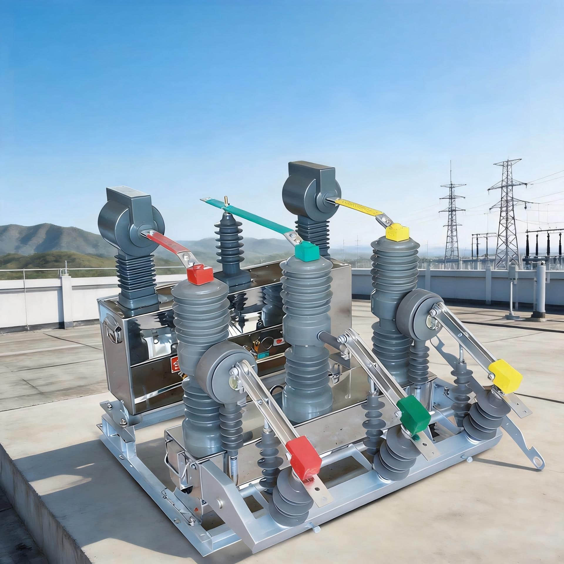
In medium-voltage power distribution, the vacuum circuit breaker is trusted for one reason above all others: it interrupts fault current quickly, cleanly, and with far less maintenance than older oil or air technologies. But when engineers, panel builders, and buyers compare models, one question keeps coming up: what operating mechanism is actually inside the breaker, and why does it matter?
This is where many purchasing mistakes begin. People often focus only on current rating, breaking capacity, or panel size, while overlooking the vacuum circuit breaker operating mechanism that determines how the breaker opens, closes, stores energy, supports remote control, and behaves under real switching duty.
In practice, the five operating modes of vacuum circuit breaker designs most commonly discussed are manual operation, motor-charged operation, spring mechanism operation, magnetic mechanism operation, and permanent-magnet mechanism operation. Each one has different implications for automation, maintenance, coil demand, lifecycle cost, and field reliability.
This article explains those five modes in a practical, engineering-focused way. It also separates operating mechanisms from trip and protection functions such as short-circuit trip, overload protection, shunt trip, undervoltage trip, anti-pumping function, and interlock systems, because these are often confused in specifications and project discussions.
Quick Answer: The 5 Operating Modes of a Vacuum Circuit Breaker
The five common operating modes of a vacuum ckt breaker are defined by how the breaker stores and releases mechanical energy for opening and closing.
Manual operation: energy is stored, and the breaker is opened or closed by hand.
Motor-charged operation: an electric motor charges the spring, enabling electrical control for closing and tripping.
Spring mechanism operation: the breaker uses stored spring energy for opening and closing; charging may be manual or motor-driven.
Magnetic mechanism operation: closing is driven by an electromagnetic actuator, typically requiring high inrush current.
Permanent-magnet mechanism operation: a magnetic actuator with fewer moving parts, known for long life and growing use in medium- and high-voltage systems.
If you need the short version: spring-operated breakers, usually with motor charging, dominate most modern medium-voltage switchgear. Manual types remain useful in simple or outdoor service situations, while permanent-magnet designs are increasingly selected where long mechanical life and reduced maintenance are priorities.
Why Understanding Vacuum Circuit Breaker Operating Modes Matters
The wrong mechanism can create a mismatch between the breaker and the application. That mismatch may not show up in a catalog comparison, but it shows up fast in the field.
For example, a manually operated breaker may be perfectly acceptable for a lightly used outdoor isolating point or maintenance switching point. But place that same mechanism in a motor control lineup requiring remote supervisory operation, frequent switching, and interlocked control logic, and it quickly becomes a limitation.
Safety is the first concern. In real installations, operators rely on controlled opening under fault conditions, visible status indication, and dependable interlocks. A breaker mechanism that cannot coordinate well with the site’s protection and control philosophy can increase operational risk.
Remote control capability is another major issue. Many industrial plants today expect breakers to interface with DCS, SCADA, PLC panels, or fire protection systems. If the breaker mechanism is not suited for electrical closing, shunt trip, or local/remote switching, automation goals fall apart.
Maintenance efficiency also depends heavily on mechanism design. A mechanism with more wear points, more adjustments, or higher coil stress can demand more periodic attention. In plants where access windows are limited, that matters more than many buyers initially think.
Protection performance is affected as well. The interruption occurs in vacuum, but the decision to open and the ability to execute the opening command reliably depend on the mechanism, trip coil path, energy storage readiness, and control circuit health.
In short, understanding vacuum circuit breaker control and protection modes starts with understanding the mechanism itself. You need to know how the breaker moves before you can fully evaluate why and when it trips.
Vacuum Circuit Breaker Operating Mechanism Basics
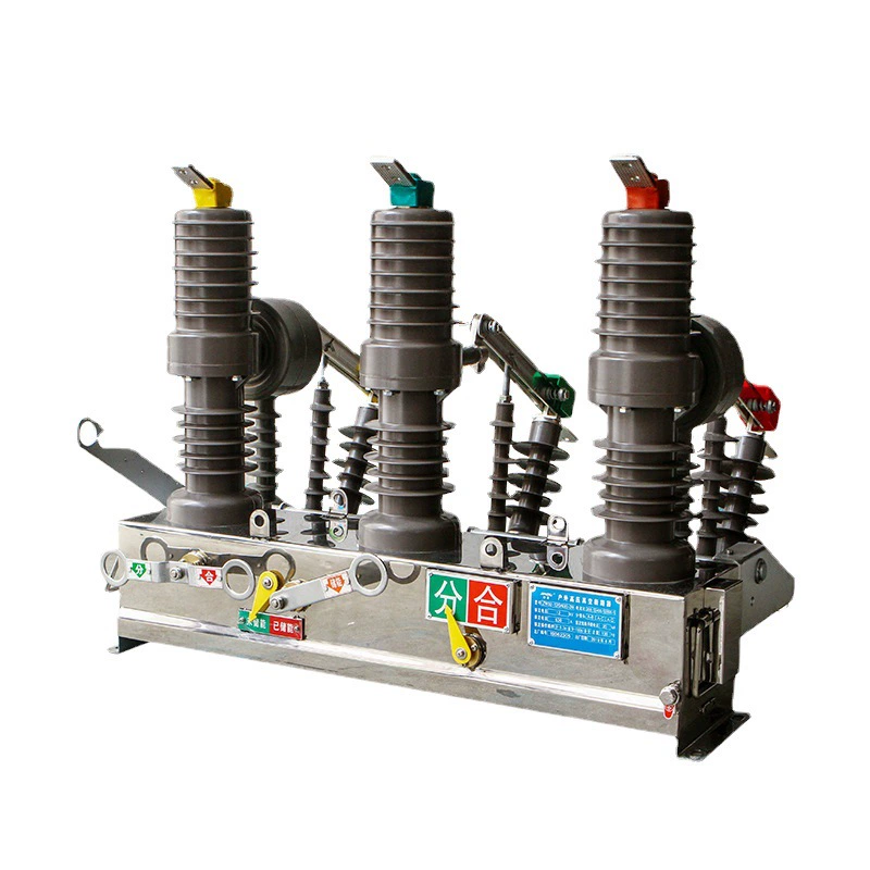
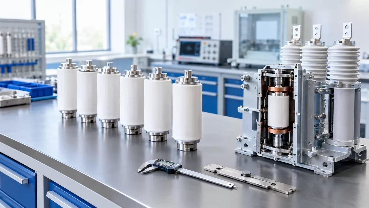
A vacuum circuit breaker interrupts current by separating contacts inside a sealed vacuum interrupter. Because there is no air or oil around the contacts, the arc extinguishes rapidly when the current passes through zero, making the technology highly effective for medium-voltage switching.
But the interrupter alone does not move. It needs an operating mechanism to provide the force and timing for vacuum circuit breaker opening and closing operations.
In a typical breaker, the mechanism performs several core tasks:
Stores mechanical energy.
Uses that energy to close the contacts.
Uses stored or released energy to open the contacts quickly.
Interfaces with trip coils, closing coils, motors, and auxiliary contacts.
Supports manual and/or electrical reset after operation.
The basic sequence is straightforward. Energy is stored in advance, usually in a spring. When a close command is given, the mechanism releases that energy to snap the contacts closed. When a trip command arrives, the latch is released and the opening spring drives the contacts apart.
This is why engineers should evaluate not only breaker ratings, but also the full chain of vacuum circuit breaker trip and reset functions, energy storage logic, and control interfaces.
Opening and Closing Operations
During closing, the breaker must overcome contact pressure, mechanism friction, and dynamic forces. In many designs, this is done by releasing stored spring energy that was charged manually or by a motor.
During opening, the operation is usually spring-driven. In many practical designs, the opening spring is already ready, and a trip coil or mechanical release unlatches the mechanism so the contacts separate at high speed.
Some breakers can also include coil-assisted functions. A shunt-trip coil allows remote opening, while the closing function may be initiated by an electrical closing coil. This distinction matters: the mechanism provides the motion, while the control coils provide the command.
Trip and Reset Functions
A breaker trips when a release signal acts on the opening latch. That signal may come from a protection relay, an intelligent controller, a fire safety input, a DCS output, or an undervoltage device.
After trip, the breaker usually requires a reset condition before reclosing. Depending on the design, reset may involve manual recharging, motor recharging of the spring, or restoration of the undervoltage release condition.
This is why vacuum circuit breaker trip and reset functions should always be checked during commissioning. A breaker may appear healthy mechanically, but if the control power, release coil, or undervoltage circuit is not correct, safe re-energization can fail.
The 5 Operating Modes of Vacuum Circuit Breaker Explained
Below is a clear comparison of the five mechanisms most commonly referenced in the market. While product designs vary by manufacturer, the core characteristics remain consistent across most medium-voltage applications.
1. Manual Operation
Manual operation means the operator charges the mechanism by hand and also performs opening and closing through a manual handle, lever, or local linkage. This is simple, direct, and independent of auxiliary control power.
In real life, manual operation is still useful in small installations, outdoor switching points, and maintenance situations. If a site has no reliable control power, or if the breaker is operated only occasionally, a manual mechanism may be entirely adequate.
The limitation is equally clear. A manual breaker generally cannot provide full remote electrical control in the same way a motor-charged or permanently actuated design can.
For rural service work, temporary switching points, and lower-duty applications, simplicity often wins. Fewer active control components can mean easier troubleshooting for field crews.
However, manual does not mean primitive. A manually operated breaker can still include position indication, auxiliary contacts, trip functions, and even protection relay coordination, depending on the architecture.
2. Motor-Charged Operation
Motor-charged operation uses an electric motor to charge the breaker’s closing spring automatically. Once charged, the breaker can be electrically closed, and opening is typically performed via the spring mechanism and trip release.
This is the mainstream configuration in modern switchgear. If a breaker is expected to work with panel control power, backend automation, SCADA, or DCS, motor charging is often the default expectation.
In practical terms, the motor reduces manual labor and ensures the breaker is ready for the next operation. In feeder panels, motor control centers with medium-voltage sections, and utility switchgear, this feature is widely preferred.
It is important to be precise here: motor charging is not always a separate operating mechanism in the strictest mechanical sense. Often, the underlying mechanism is still spring-operated, and the motor is simply the charging method. Yet in the market, buyers commonly refer to this as a distinct operating mode because it changes how the breaker is used in the field.
3. Spring Mechanism Operation
Spring mechanism operation is the most common vacuum circuit breaker operating mechanism. A charged spring stores the energy needed for closing, and an opening spring provides the force for trip opening.
This design is popular because it balances reliability, cost, response speed, and automation compatibility. It can support both manual charging and motor charging, giving it flexibility across many project types.
Most modern medium-voltage switchgear from 6 kV to 36 kV uses some variation of this approach. In utility feeders, transformer incomers, capacitor banks, and industrial distribution panels, spring-operated vacuum breakers remain the workhorse of the market.
For many buyers, this is the safest default choice. It is proven, widely understood by service teams, and supported by common relay and control schemes.
4. Magnetic Mechanism Operation
Magnetic mechanism operation relies on electromagnetic force, typically through a closing electromagnet, to actuate the breaker. Historically, this offered a workable alternative to some purely spring-based arrangements.
Its main disadvantage is the need for a high closing current. That means more stress on the control supply and potentially larger demands on the switching circuit.
Because of that, magnetic operating mechanisms are used less often today. In many modern projects, engineers prefer mechanisms that deliver lower control burden, simpler maintenance, and better lifecycle economics.
That said, magnetic systems still appear in some legacy installations or specialized designs. When replacing existing switchgear, compatibility with installed control circuits can still make them relevant.
5. Permanent-Magnet Mechanism Operation
Permanent-magnet mechanism operation uses a magnetic actuator that typically has a simpler structure and fewer parts than many conventional mechanical systems. This reduction in moving components is one of its strongest selling points.
In medium- and high-voltage applications, permanent-magnet designs are valued for long service life, stable actuation characteristics, and reduced mechanical wear. For facilities that prioritize maintenance reduction, this can be very attractive.
These mechanisms are increasingly used in advanced switchgear, especially where operation frequency is high or lifecycle cost matters more than lowest first price. They are also well suited to digitally managed substations and premium industrial panels.
When discussing long-life medium-voltage solutions with project teams, manufacturers such as Weisho Electric are often evaluated not only on breaker ratings, but also on how effectively the chosen mechanism supports field reliability, spares strategy, and control integration.
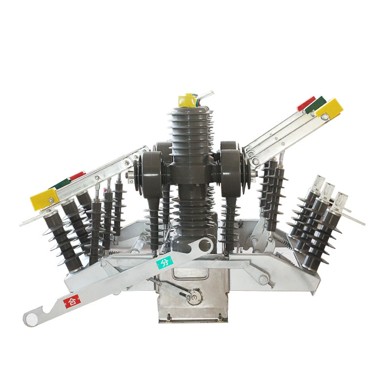
Table: Comparison of the 5 Vacuum Circuit Breaker Operating Modes
| OPERATING MODE | MAIN ENERGY SOURCE | REMOTE CONTROL CAPABILITY | RELIABILITY | MAINTENANCE LEVEL | RESPONSE SPEED | COMMON APPLICATIONS |
|---|---|---|---|---|---|---|
| Manual Operation | Human manual charging and actuation | Low | Good in simple low-duty use | Low to moderate | Operator dependent | Outdoor maintenance points, low-duty service, simple installations |
| Motor-Charged Operation | Motor charges spring; electrical close/trip control | High | High | Moderate | Fast and consistent | Industrial switchgear, utility feeders, motor control lineups |
| Spring Mechanism Operation | Stored spring energy | Medium to high | Very high | Moderate | Fast | Mainstream medium-voltage switchgear |
| Magnetic Mechanism Operation | Electromagnetic closing force | Medium | Moderate | Moderate to high | Fast | Legacy systems, selected special applications |
| Permanent-Magnet Mechanism | Magnetic actuator with permanent magnet holding/actuation | High | Very high | Low | Very fast and repeatable | Advanced MV switchgear, premium industrial and utility applications |
Which Vacuum Circuit Breaker Operating Mode Is Most Common?
The most common modern solution is the spring-operated vacuum circuit breaker, usually with motor charging. This combination dominates because it offers a practical balance of cost, automation, reliability, and service familiarity.
In medium-voltage switchgear for 11 kV, 12 kV, 24 kV, and 36 kV systems, this design is seen across utility substations, manufacturing plants, commercial infrastructure, mining sites, and renewable energy collection networks.
Why is it so dominant?
Reliable stored-energy operation is well proven.
Remote electrical control is easy to implement.
Protection relay coordination is straightforward.
Spare parts and service knowledge are widely available.
Total ownership cost is usually competitive.
For most buyers, the real comparison is not “manual versus all others.” It is usually standard motor-charged spring mechanism versus permanent-magnet mechanism, especially in newer medium-voltage projects.
Vacuum Circuit Breaker Control and Protection Modes
One of the biggest sources of confusion in the market is this: operating mechanisms are not the same as protection functions. The mechanism describes how the breaker moves. The protection and control functions describe what commands it to move, under what conditions, and with what logic.
Understanding this difference is essential when specifying a vacuum circuit breaker. Below are the key electrical and tripping functions often discussed together with operating modes.
Short-Circuit Trip
Short-circuit trip is the rapid opening of the breaker when a fault current exceeds the protection threshold. In practice, a relay detects the fault and energizes the trip coil, releasing the breaker mechanism.
For medium-voltage systems, relay operating times can be in the tens of milliseconds, depending on settings and selectivity. The breaker mechanism must then execute the opening command quickly enough to clear the fault within the required interruption duty.
Overload Protection
Overload protection is usually not built into the breaker mechanism itself. Instead, it is provided by an external protection relay or intelligent electronic device that monitors current over time and trips the breaker when thermal limits are exceeded.
This is especially common on transformer feeders, motor feeders, and distribution circuits where inverse-time characteristics are needed. The breaker is the switching device; the relay provides the decision logic.
Shunt Trip
Shunt trip is a remote trip function. An external electrical signal energizes the trip coil and causes the breaker to open.
This is widely used for fire systems, DCS remote shutdown, SCADA commands, and emergency stop logic. In many industrial projects, the shunt-trip input is one of the most important interfaces in the breaker control circuit.
Undervoltage Trip
Undervoltage trip automatically opens the breaker if control voltage is lost or drops below a defined threshold. This protects systems from unsafe or unintended operation when supply conditions collapse.
In transfer schemes and certain motor applications, undervoltage release is critical. It ensures the breaker does not remain closed when required control conditions are no longer present.
Over-Current Protection
Over-current protection is broader than short-circuit trip alone. It includes phase overcurrent, earth fault, and time-coordinated protection functions configured in the relay.
In feeder and transformer protection schemes, over-current elements are set to coordinate with upstream and downstream devices. The breaker mechanism must be dependable, but the actual protective intelligence resides in the relay settings.
Anti-Pumping Function
Anti-pumping function prevents repeated close-open-close cycling when a closing signal remains present during a persistent fault or unsuccessful closing attempt. Without anti-pumping, the breaker may repeatedly attempt to reclose into a faulted circuit.
This is a crucial safety and equipment protection feature in electrically controlled breakers. It avoids damaging repeated mechanical operation and helps maintain orderly control behavior.
Interlock Systems
Interlock systems prevent unsafe switching sequences. These may be mechanical, electrical, or both.
Examples include preventing the breaker from closing onto an engaged earthing switch, preventing withdrawal of the breaker truck in the closed position, or blocking door opening while live parts remain energized. In metal-clad switchgear, these interlocks are as important as the breaker itself.
Local and Remote Control
Local and remote control allows operation from panel-mounted pushbuttons as well as from backend systems such as SCADA, PLC, DCS, or substation control platforms.
In a well-designed control scheme, local/remote selection is clear, status feedback is reliable, and command priority is defined. This matters greatly in plants where both control room operators and field technicians may interact with the same breaker.
Position Indicator
Position indicator provides a mechanical or visual indication of whether the breaker is open or closed. Operators should never rely only on software signals when standing in front of the cubicle.
A robust mechanical position indicator remains one of the simplest and most trusted safety features in switchgear operation.
Spring Charged Indicator
A spring-charged indicator shows whether the stored-energy spring is charged or discharged. This is essential before performing a close command or before maintenance work.
On many spring-operated designs, this indicator is easy to overlook, but experienced technicians check it instinctively because it immediately tells them if the breaker is ready for the next operation.
Auxiliary Contacts
Auxiliary contacts provide feedback for breaker status, alarm indication, interlock logic, and control integration. These contacts do not carry the main circuit current; they carry signaling information.
They are used for open/close confirmation, spring-charged status, remote annunciation, permissive interlocks, and protection logic. In automated installations, auxiliary contacts are fundamental.
Table: Operating Modes vs Protection Functions
| ITEM | CATEGORY | WHAT IT DESCRIBES | EXAMPLES |
|---|---|---|---|
| Manual operation | Operating mechanism | How the breaker is charged and actuated | Hand charging, manual open/close |
| Motor-charged operation | Operating mechanism / charging method | How stored energy is prepared for closing | Motor charges spring automatically |
| Spring mechanism | Operating mechanism | How motion energy is stored and released | Closing spring, opening spring |
| Magnetic mechanism | Operating mechanism | How electromagnetic force moves the breaker | Closing electromagnet |
| Permanent-magnet mechanism | Operating mechanism | How magnetic actuation drives operation | Permanent-magnet actuator |
| Short-circuit trip | Protection function | Why the breaker opens | Relay trips on fault current |
| Overload protection | Protection function | Why the breaker opens after thermal overload timing | Inverse-time relay action |
| Shunt trip | Control / trip function | How a remote signal commands opening | Fire alarm, DCS shutdown |
| Undervoltage trip | Control / protective release | Why the breaker opens on low or lost voltage | Control supply collapse |
| Anti-pumping | Control logic | How repeated reclosing is prevented | Blocks repeat close attempts |
Real-World Examples of Vacuum Circuit Breaker Operating Mode Selection
Catalog descriptions are useful, but real applications make the differences clearer. Below are practical examples based on common medium-voltage project scenarios.
Example: Industrial Motor Control Lineup
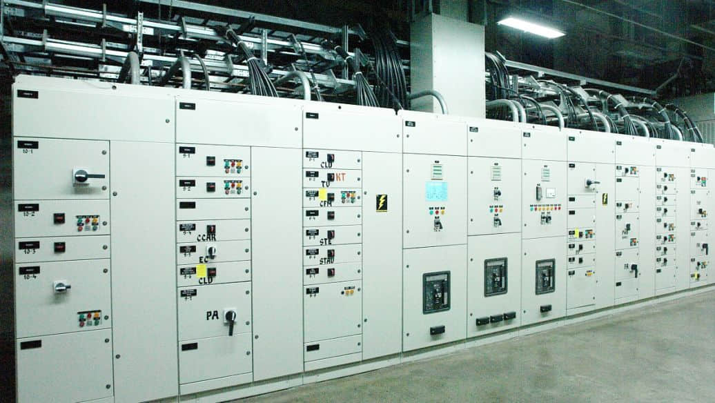
Consider a 6.6 kV or 11 kV motor control lineup in a cement plant, steel mill, water treatment facility, or mining operation. Large motors may require frequent switching for process control, planned shutdowns, and protective trips.
In this environment, motor-charged spring mechanisms are usually preferred. They support electrical closing, rapid recharging, local/remote control, shunt trip integration, and smooth coordination with intelligent motor protection relays.
For example, many medium-voltage motor feeders in industrial plants are expected to support breaker operation counts far above what a low-duty manual device would comfortably handle. A motor-charged spring mechanism reduces operator intervention and supports centralized control room operation.
If a plant uses DCS-based start/stop permissives, anti-pumping logic, and status feedback to a historian, the breaker must do more than interrupt current. It must behave as a dependable electromechanical endpoint in the automation chain.
Example: Rural Pole-Mounted or Outdoor Service Work
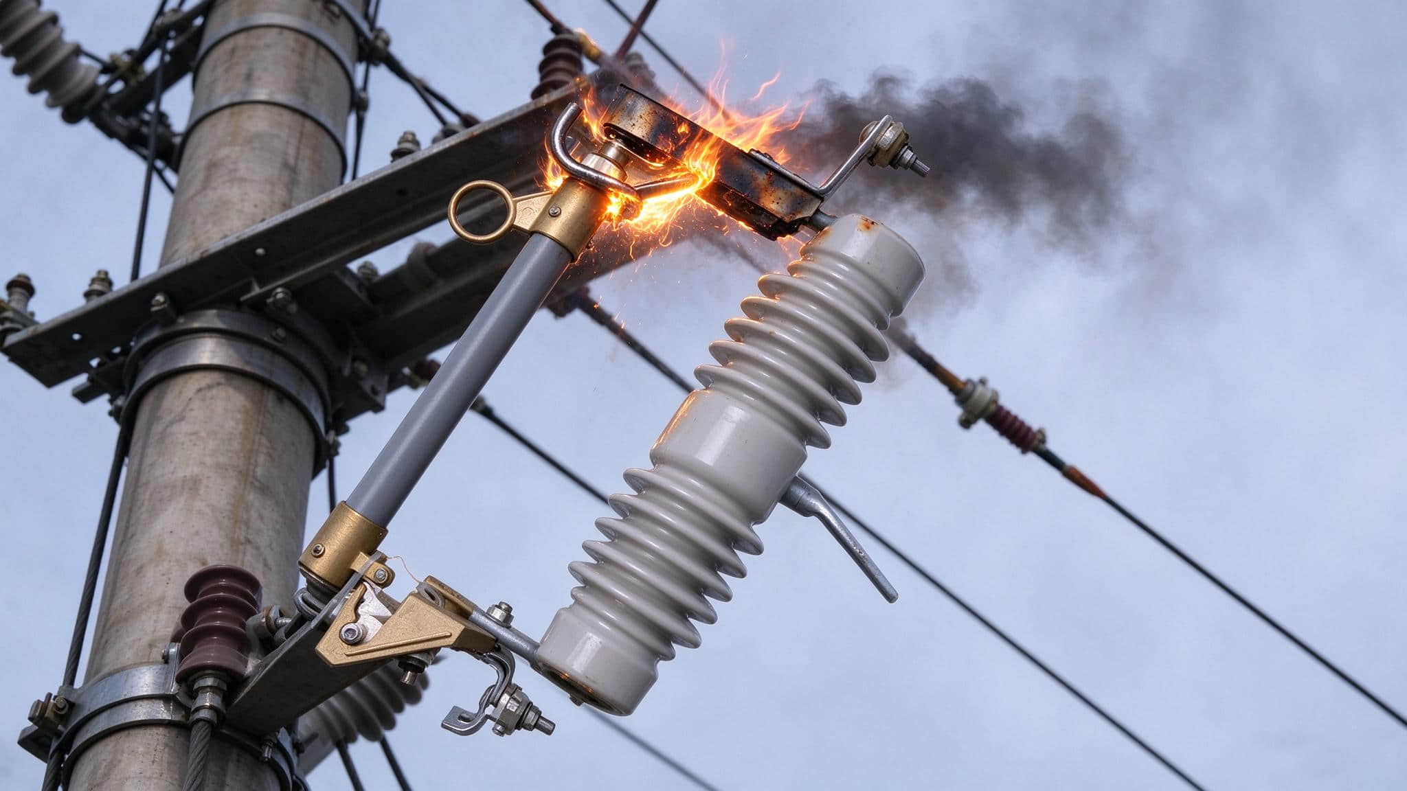
Now consider a rural service branch, temporary maintenance arrangement, or outdoor switching point where auxiliary control power is not dependable. In these cases, manual operation can still make excellent sense.
The priority is simplicity. Crews may prefer a mechanism that can be charged and operated directly without relying on batteries, chargers, or cabinet-mounted control supplies.
This does not mean protection is absent. A manually operated breaker may still work with external relay logic or be used in a limited-duty point where manual switching is the main requirement and fault clearing strategy is managed elsewhere in the system design.
Example: Modern Medium-Voltage Switchgear
In a modern utility substation or premium industrial switchboard, the discussion often shifts toward spring mechanisms versus permanent-magnet mechanisms. The deciding factors are usually lifecycle expectations, maintenance strategy, and switching duty.
Permanent-magnet designs attract attention where operators want fewer moving parts and long mechanical endurance. Spring mechanisms remain attractive where proven familiarity, broad service support, and lower first cost are priorities.
In competitive projects, engineering teams may compare conventional motor-charged spring breakers with newer actuator styles from manufacturers including Weisho Electric, especially when the owner’s specification emphasizes reduced maintenance interventions over a 15- to 25-year equipment horizon.
Table: Typical Application Scenarios and Recommended Operating Mode
| APPLICATION SCENARIO | TYPICAL VOLTAGE CLASS | OPERATION FREQUENCY | REMOTE CONTROL NEEDED | RECOMMENDED MECHANISM |
|---|---|---|---|---|
| Temporary outdoor maintenance point | 3.6 kV to 12 kV | Low | No | Manual operation |
| Industrial feeder panel | 6.6 kV to 24 kV | Moderate | Yes | Motor-charged spring mechanism |
| Utility metal-clad switchgear | 11 kV to 36 kV | Moderate | Yes | Spring mechanism, usually motor charged |
| Premium digital substation | 12 kV to 40.5 kV | Moderate to high | Yes | Permanent-magnet mechanism |
| Legacy retrofit with existing magnetic control scheme | Older MV systems | Moderate | Possibly | Magnetic mechanism where compatibility requires it |
| Rural service switching | 7.2 kV to 15 kV | Low | Usually no | Manual operation |
Data and Performance Benchmarks for Vacuum Ckt Breaker Mechanisms
Mechanism selection should not be based on theory alone. Buyers should compare actual performance indicators such as mechanical life, control power demand, service intervals, and actuation repeatability.
Below are indicative market-level figures drawn from common medium-voltage switchgear specifications, product catalogs, and industry practice. Exact values vary by design, rating, and manufacturer, but the ranges are useful for decision-making.
Typical Mechanical Life Range by Mechanism
Mechanical life is often expressed as the number of operating cycles under no-load or standard test conditions. In medium-voltage breaker catalogs, values commonly range from 10,000 to 30,000 operations, with premium designs sometimes exceeding that.
| MECHANISM TYPE | INDICATIVE MECHANICAL LIFE RANGE | MARKET OBSERVATION |
|---|---|---|
| Manual operation | 5,000 to 10,000 operations | Suitable for low-frequency duty |
| Motor-charged spring | 10,000 to 20,000 operations | Mainstream industrial and utility range |
| Spring mechanism | 10,000 to 30,000 operations | Broadest market presence and proven durability |
| Magnetic mechanism | 10,000 to 15,000 operations | More dependent on coil and system condition |
| Permanent-magnet mechanism | 20,000 to 50,000 operations | Often promoted for long-life duty |
In actual service, operation count depends heavily on application. A transformer incomer may operate relatively infrequently, while a motor feeder or process switching breaker may accumulate cycles much faster.
Typical Control Power and Coil Demand
Control power requirements affect cabinet design, battery sizing, UPS planning, and auxiliary circuit reliability. This is one reason magnetic mechanisms have declined in popularity.
| MECHANISM TYPE | CHARGING POWER NEED | CLOSING COIL / ACTUATION DEMAND | TYPICAL CONTROL POWER COMMENT |
|---|---|---|---|
| Manual operation | None for charging | Low to none for purely manual close | Best where no auxiliary supply is available |
| Motor-charged spring | Commonly tens to a few hundred watts during charging | Moderate momentary coil demand | Well suited to standard AC/DC control supplies |
| Spring mechanism | Manual or motor charged | Moderate | Flexible across many schemes |
| Magnetic mechanism | Not spring-dominant | High inrush current for electromagnetic closing | Can stress control systems more heavily |
| Permanent-magnet mechanism | Low continuous need; pulse-based actuation in many designs | Controlled actuation pulse | Efficient in advanced control systems |
Typical Maintenance and Reliability Trends
Maintenance is not only about the interrupter bottle. It is often the mechanism, auxiliary switches, latches, and linkages that determine how often service teams must intervene.
| MECHANISM TYPE | PARTS COUNT | MAIN WEAR POINTS | EXPECTED SERVICE COMPLEXITY | RELIABILITY TREND |
|---|---|---|---|---|
| Manual operation | Low | Linkages, latch points, manual handles | Low | Reliable in simple low-duty service |
| Motor-charged spring | Moderate | Motor, gears, springs, latch system, coils | Moderate | High when maintained properly |
| Spring mechanism | Moderate | Spring pack, latch surfaces, auxiliary switches | Moderate | Very strong field record |
| Magnetic mechanism | Moderate | Coils, magnetic actuator components, control supply interface | Moderate to high | Adequate but less favored today |
| Permanent-magnet mechanism | Low to moderate | Actuator assembly, electronic control interface | Low to moderate | Excellent where design quality is high |
How to Choose the Right Vacuum Circuit Breaker Operating Mode
The right selection comes down to five questions:
What is the voltage class and fault duty?
How often will the breaker operate?
Do you need local only, or local plus remote control?
How much maintenance capability does the site have?
How tightly must the breaker integrate with relay and automation systems?
If you answer those five clearly, mechanism selection becomes much easier.
If You Need Low Cost and Simplicity
Choose manual operation when the application is low-duty, cost-sensitive, and not dependent on remote electrical control. This works best for simple installations, outdoor switching, isolated service points, and maintenance use.
It is especially attractive where auxiliary power is unavailable or not worth the added complexity. Just be honest about the operational limitations before specifying it.
If You Need Standard Utility or Industrial Performance
Choose a spring mechanism with motor charging. This is the default solution for most medium-voltage utility and industrial projects.
It supports local and remote operation, reliable trip behavior, strong relay integration, and familiar maintenance practices. For most buyers, this is the safest and most economical mainstream answer.
If You Need High Reliability with Fewer Mechanical Parts
Choose a permanent-magnet mechanism for advanced medium-voltage systems where long mechanical life, low maintenance, and repeatable operation are high priorities.
This option often fits premium switchgear, digital substations, and applications where lifecycle performance matters more than minimum upfront cost.
Common Mistakes When Identifying Vacuum Circuit Breaker Modes
The most common mistake is mixing up operating mode with trip function. A breaker does not have “shunt trip instead of spring mechanism.” Those are different layers of the design.
Another mistake is assuming that motor-charged and spring-operated are mutually exclusive. In reality, many of the most common breakers are spring-operated breakers with motor charging.
A third mistake is choosing manual operation based only on initial cost. If the site later needs remote control, fire-system trip input, or frequent switching, the savings disappear quickly.
There is also a tendency to compare magnetic and permanent-magnet mechanisms without reviewing actual control power conditions. Magnetic mechanisms may require substantially higher actuation demand, which can complicate the auxiliary system design.
Finally, buyers sometimes overlook indicators and interlocks. A breaker is not fully evaluated until you confirm position indication, spring charged indication, auxiliary contacts, local/remote logic, and interlock integrity.
FAQ
What are the five operating modes of a vacuum circuit breaker?
The five common operating modes are manual operation, motor-charged operation, spring mechanism operation, magnetic mechanism operation, and permanent-magnet mechanism operation.
Is a spring mechanism the same as a motor-charged vacuum circuit breaker?
No. The spring mechanism is the stored-energy operating mechanism, while motor charging is the method used to charge that spring automatically in many modern breakers.
Which vacuum circuit breaker operating mode is best for remote control?
Motor-charged spring mechanisms and permanent-magnet mechanisms are usually the best choices for remote control because they integrate well with electrical closing, tripping, and automation systems.
What is the difference between shunt trip and undervoltage trip in a vacuum circuit breaker?
Shunt trip opens the breaker when an external command energizes the trip coil, while undervoltage trip opens the breaker automatically when the control voltage is lost or falls below the set threshold.
Are protection functions the same as operating modes in a vacuum ckt breaker?
No. Operating modes describe how the breaker physically opens and closes, while protection functions describe why it trips and what control logic commands the operation.
Why are magnetic operating mechanisms used less often today?
They are used less often because they typically require higher closing current, place greater demand on control circuits, and are often less attractive than spring or permanent-magnet alternatives in modern installations.
Can a manual vacuum circuit breaker still have trip protection?
Yes. A manual breaker can still work with protection relays, trip devices, and release functions depending on the design, even if closing and charging are performed manually.
What indicators should I check before operating a vacuum circuit breaker?
Check the open/closed position indicator, spring charged indicator, control power availability, and interlock condition before operating the breaker.
Conclusion: Choosing the Best Vacuum Circuit Breaker Operating Mode
The best vacuum circuit breaker operating mode is not the one with the most advanced label. It is the one that fits the application’s real needs for control method, protection integration, operating frequency, maintenance capability, and reliability target.
If the duty is light and simplicity matters most, manual operation still has a place. If you need the mainstream answer for medium-voltage switchgear, a spring-operated breaker with motor charging remains the standard choice. If the project values long life and fewer mechanical parts, permanent-magnet technology deserves close attention.
Above all, keep one principle clear: operating mechanisms and protection functions must be evaluated separately, then designed to work together. That is how safe, dependable breaker performance is achieved over the full life of the installation.
CTA: Need Help Selecting the Right Vacuum Circuit Breaker?
If you are comparing vacuum ckt breaker options for switchgear, substations, motor feeders, transformer panels, or outdoor service applications, now is the time to look beyond basic ratings and choose the right operating mechanism with confidence.
Contact our team today to compare specifications, review control and trip requirements, and identify the most suitable vacuum circuit breaker control and protection modes for your project. Whether you need a proven spring-operated design, a remote-control-ready motor-charged breaker, or a long-life permanent-magnet solution, we can help you select the right configuration faster and with fewer risks.
Request expert guidance now, send your technical requirements, and get the best vacuum circuit breaker solution for your application.