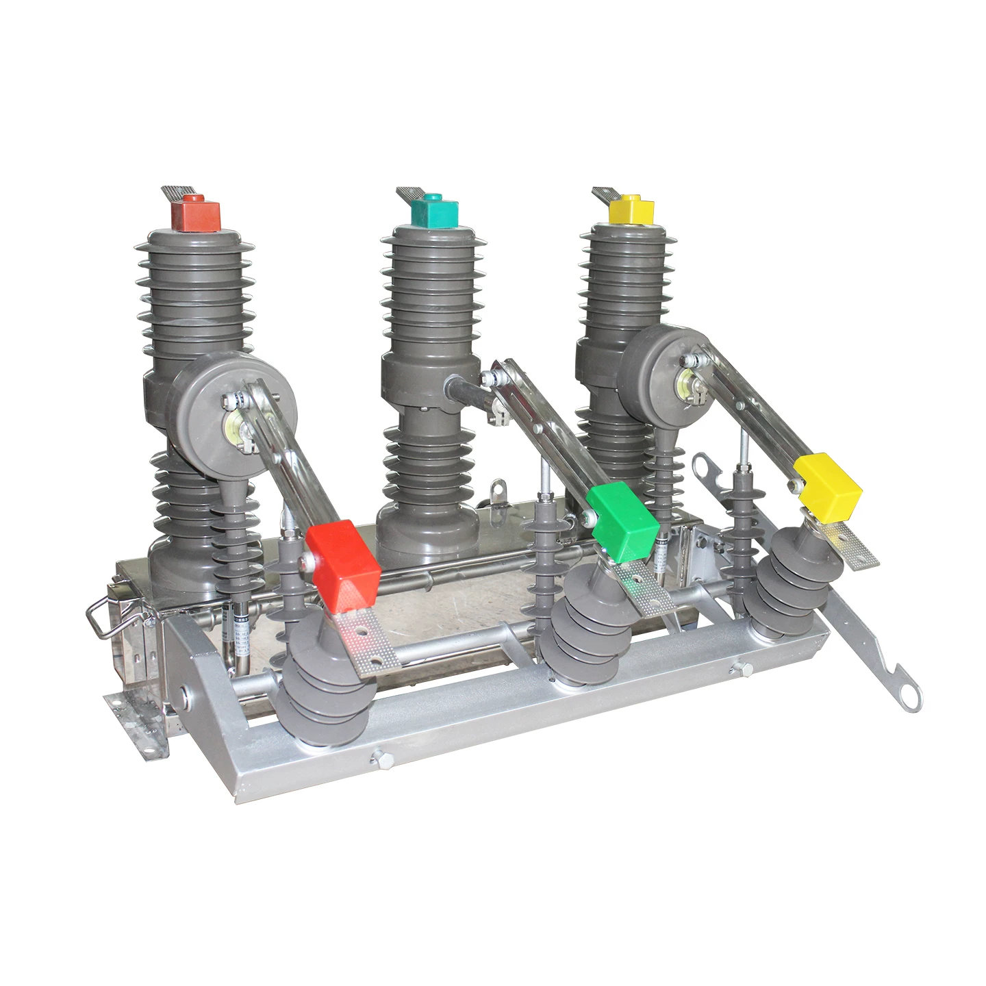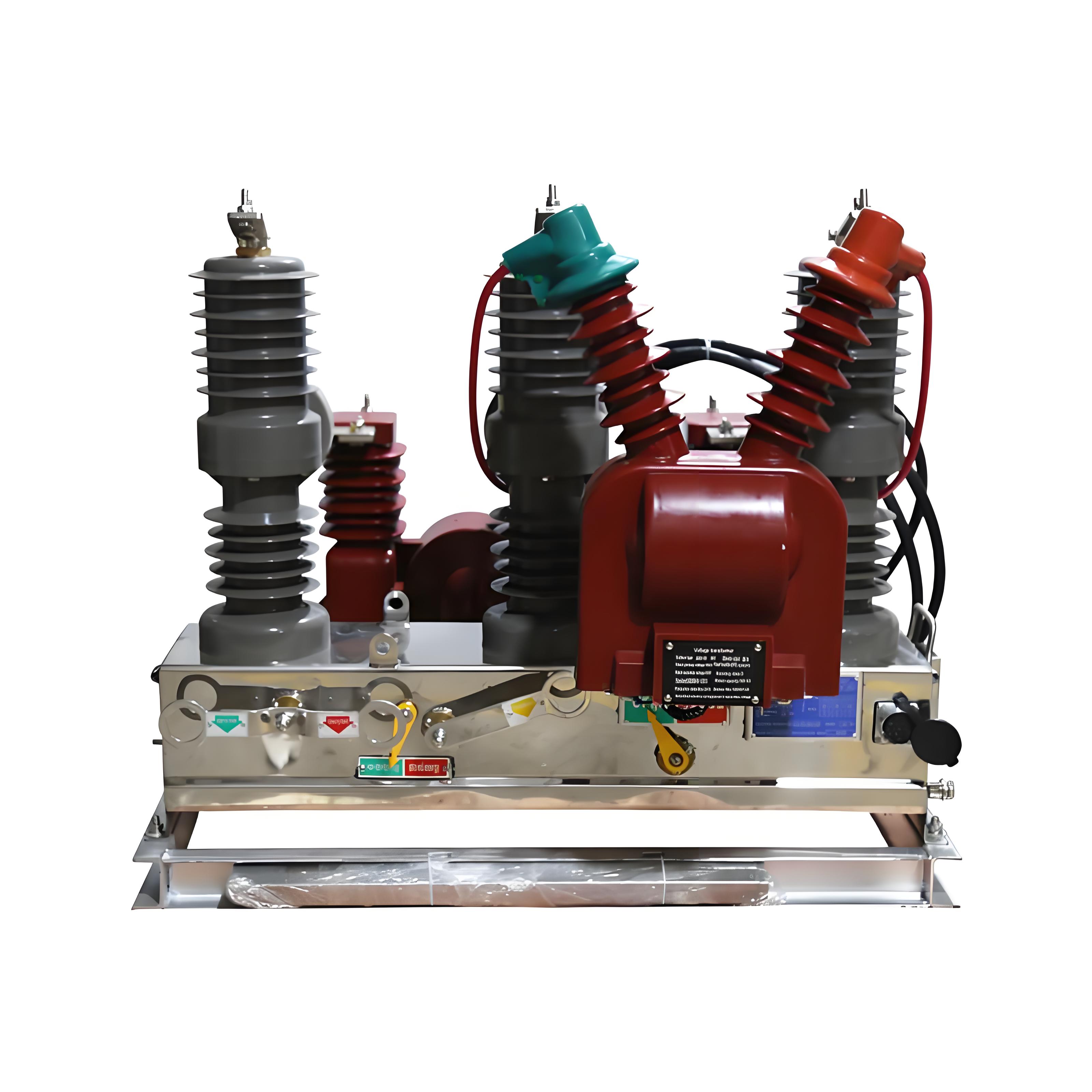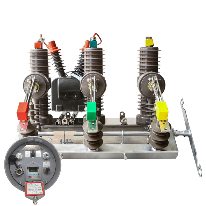
In many medium-voltage substations, a vacuum circuit breaker looks deceptively simple. It opens, closes, trips when needed, and often runs for years with little visible trouble.
That is exactly why it can become a hidden hazard.
When a breaker is assumed to be “maintenance-free,” small defects accumulate quietly. Overvoltage during switching, loss of vacuum, contact wear, rebound, and abnormal operating speed can all turn reliable equipment into a source of insulation failure, feeder outage, transformer damage, or even switchgear fire risk.
This article is built as a practical, field-oriented guide for engineers, maintenance managers, plant electricians, and utility technicians. It follows real operating logic, not generic theory, and it is designed to function as a working vacuum circuit breaker maintenance checklist as well as a reference for identifying hidden hazards in medium voltage switchgear.
If your site operates 10 kV class switchgear, capacitor banks, transformers, ring main units, or motor feeders, these seven preventive steps are not optional best practices. They are the difference between controlled maintenance and emergency failure response.
Why Vacuum Circuit Breakers Become Hidden Hazards
Vacuum circuit breakers are widely used because they offer compact size, strong interrupting performance, and comparatively low routine servicing demands. But “low maintenance” never means “no maintenance.”
The hidden danger comes from the fact that several failure mechanisms develop internally or mechanically before operators notice obvious symptoms.
A classic example is switching overvoltage. When a vacuum circuit breaker interrupts a very small inductive current, such as the magnetizing current of an unloaded transformer, current chopping can create steep transient overvoltage.
When it switches a capacitor bank, the interruption of capacitive current may trigger restrike overvoltage. In a real plant, this may not damage the breaker immediately, but it can progressively stress connected transformer insulation, PTs, cable terminations, and surge arresters.
Another hidden hazard is vacuum loss inside the vacuum interrupter. The interrupter depends on a high vacuum, typically around 10⁻⁴ to 10⁻⁶ Pa, to maintain dielectric strength and interrupt current properly.
Once that vacuum level degrades, the breaker may still appear mechanically normal. Yet its withstand voltage drops, interrupting performance weakens, and internal flashover risk rises sharply.
Then there is contact wear. Every interruption consumes a tiny portion of contact material. In frequent switching applications such as motor control, capacitor switching, furnace feeders, or repeated fault clearing, the cumulative wear is not theoretical. It is measurable.
Mechanical issues are equally important. Incorrect contact overtravel, spring deformation, poor contact pressure, excessive opening or closing rebound, and abnormal operating speed all accelerate deterioration.
These issues often lead to a chain reaction: higher contact resistance, overheating, vibration, contact bounce, surface damage, and ultimately vacuum interrupter failure or mechanism failure.
This is why robust vacuum circuit breaker safety inspection procedures are essential. They are not just for compliance. They are the primary defense against faults that otherwise stay invisible until the day the breaker fails to clear, fails to close, or damages connected equipment.
The Fast Warning Signs of Vacuum Interrupter Failure
In practice, experienced technicians rarely wait for a catastrophic fault. They look for fast warning signs.
Some are visible. Some appear only in test data. Some reveal themselves through sound, temperature, or operating behavior.
One important indicator, especially on older glass-envelope interrupters, is arc-color change. Under normal vacuum conditions, the shield is relatively bright, and the arc often appears light blue.
If the vacuum deteriorates severely, the shield may darken and the arc can shift toward a dull red color. This is not a subtle cosmetic detail. It is a classic vacuum interrupter failure warning sign.
Another red flag is darkening of the shield. If the shield appearance has changed noticeably during maintenance inspection, vacuum integrity must be questioned and follow-up testing is necessary.
Abnormal noise during operation is equally important. A healthy vacuum circuit breaker has a consistent mechanical sound profile. A new metallic knock, rebound noise, scraping, delayed latch action, or abnormal buzz can indicate mechanism wear, misalignment, spring issues, or internal interrupter damage.
Overheating leads or terminals are often overlooked. Infrared scans repeatedly show that many “breaker problems” first appear as a temperature rise at the connection point, conductive rod, or contact path.
If circuit resistance rises because of contact wear, poor pressure, contamination, looseness, or conductive path deformation, heat follows. At 10 kV switchgear level, even modest extra resistance can become dangerous under high load.
Increasing loop resistance is therefore more than a test number. It is a trend indicator. If measured resistance steadily climbs over successive inspections, something inside the current path is changing, and that change should be investigated before a thermal failure occurs.
A failed power-frequency withstand test is another major warning. If the interrupter cannot pass the specified withstand test, particularly after reconditioning, it should not remain in service.
Finally, watch the mechanism. Slow closing, fast opening beyond tolerance, incomplete travel, irregular speed, visible bounce, or unstable position indication all suggest the breaker can no longer be trusted simply because it still operates.
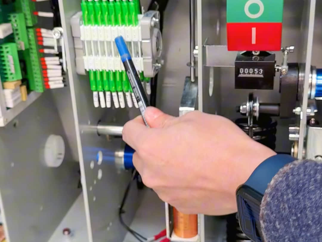
The 7 Preventive Maintenance Steps for Vacuum Circuit Breakers
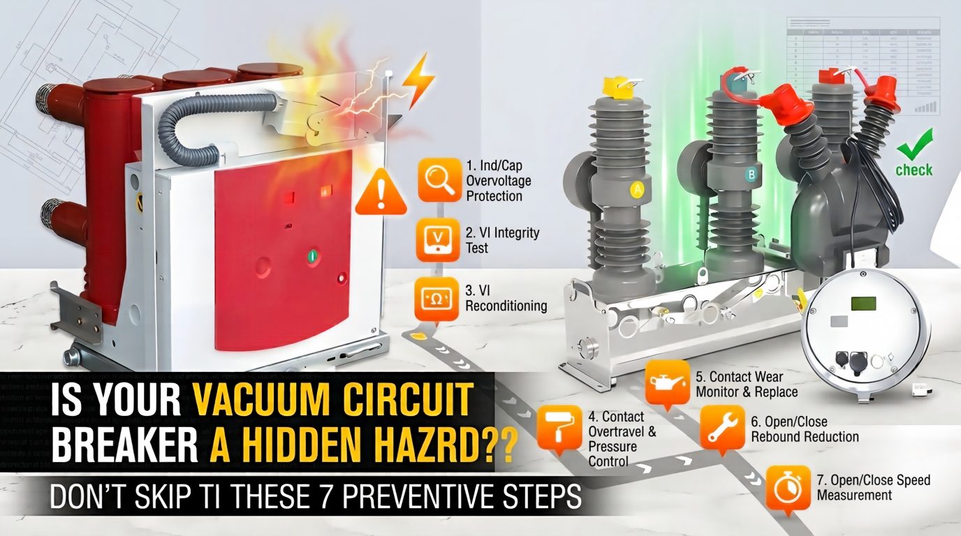
The following seven actions form the core preventive maintenance steps for vacuum circuit breakers. In the field, these steps are the most effective way to detect hidden defects before they become operational incidents.
1. Install Overvoltage Protection for Small Inductive and Capacitive Switching
Vacuum circuit breakers are excellent interrupters, but that same fast dielectric recovery can create a switching overvoltage problem in certain duties.
When interrupting small inductive current, such as unloaded transformer magnetizing current, the breaker may chop current before natural current zero. This generates current-chopping overvoltage.
When switching capacitor banks, the circuit may experience restrike overvoltage. Even one restrike event can create a severe transient, especially where cable lengths, harmonics, or bank configuration magnify surge behavior.
Good practice is to install metal-oxide surge arresters with appropriate protection characteristics, or use RC protection devices where specified by system design.
In actual utility applications, restrike during capacitor bank switching has caused fuse operation, blown capacitor elements, and repeated stress on connected PTs. These incidents are often wrongly blamed on “poor power quality” when the real issue is inadequate switching surge control.
If your breaker frequently switches unloaded transformers, reactor branches, or capacitor banks, overvoltage protection is not an accessory. It is basic risk control.
2. Test Vacuum Integrity of the Vacuum Interrupter Regularly
The vacuum interrupter must maintain a vacuum level typically in the range of 10⁻⁴ to 10⁻⁶ Pa. If that vacuum degrades, both dielectric strength and interrupting capability decline.
For glass-envelope interrupters, a visual method can offer a quick screening reference. Under normal condition, the internal shield appears bright and the arc is usually light blue.
Under severe vacuum loss, the shield may look darker and the arc becomes dark red. This visual method is not a complete diagnostic tool, but it is useful as a first alert.
More importantly, sites should perform power-frequency withstand testing on a regular basis. A common maintenance reference is a 42 kV withstand test approximately every three years for 10 kV class equipment, subject to manufacturer and local standard requirements.
If the interrupter fails to meet the withstand requirement, and still does not recover after repeated conditioning, it must be replaced.
This step is one of the most important items in any serious vacuum circuit breaker maintenance checklist. Vacuum loss is often invisible until a fault occurs. Regular testing turns an invisible risk into an actionable maintenance decision.
3. Recondition the Vacuum Interrupter After Storage or Before Commissioning
Many engineers assume that a new vacuum interrupter needs no further treatment because it was factory-conditioned before shipment. In reality, that assumption can be expensive.
After long storage, transport vibration, humidity exposure, warehouse contamination, or delayed installation, dielectric performance may no longer be at its original level. The interrupter may look perfect but still fail commissioning tests.
That is why voltage conditioning and the specified power-frequency withstand test should be carried out after installation or before energization, especially for stock that has been stored for extended periods.
Field teams have seen breakers that sat in storage for 18 to 24 months fail first-pass withstand testing, then pass after proper conditioning and repeated preparation. Without that step, the same breaker might have entered service with reduced margin.
This is not overcautious maintenance. It is disciplined commissioning.
4. Control Contact Overtravel and Contact Pressure Precisely
For a typical 10 kV vacuum interrupter, the common reference values are about 3 mm contact overtravel and about 12 mm contact gap. These are not rough suggestions.
They directly influence contact pressure, closing force, interrupter stress, and electrical performance.
If overtravel is set too low, contact pressure may be insufficient. That can lead to overheating, rising resistance, unstable conduction, and accelerated contact wear.
If overtravel is set too high, the mechanism may overload the interrupter structure, increasing mechanical stress and shortening service life.
During installation or repair, technicians must adjust overtravel according to the manufacturer’s instructions. The contact spring should also be checked carefully for deformation, fatigue, or improper replacement.
Never change this setting casually in the field to “make it close better.” Improvised adjustment is one of the most common causes of poor performance after maintenance.
Manufacturers such as Weisho Electric and other established medium-voltage equipment suppliers typically define these values clearly in technical documentation. Following those values exactly is far more reliable than relying on workshop habit or guesswork.
5. Track Contact Wear and Replace Before the Limit
Contact wear is cumulative, measurable, and one of the most underestimated breaker health indicators.
After repeated interruption, the maximum contact wear may approach about 3 mm. Once the wear reaches or exceeds that value, the interrupter should be replaced.
The key point is not just knowing the replacement limit. It is establishing a baseline measurement at installation and then tracking wear at every major inspection.
Without a baseline, maintenance teams can only guess whether contact erosion is minor or critical. With a baseline, wear trend becomes obvious.
Loop resistance testing is also helpful as a supporting indicator. If measured resistance rises together with wear evidence or thermal imaging anomalies, the replacement case becomes stronger.
In one industrial feeder application with frequent motor starts, a breaker that still “operated normally” showed unacceptable contact wear after repeated duty cycles. Infrared inspection later confirmed abnormal heating under load. The breaker had not yet failed, but it had clearly crossed from reliable service into hidden-risk territory.
6. Reduce Opening and Closing Rebound
Rebound is more destructive than many maintenance teams realize.
During opening or closing, excessive bounce can cause contact burning, contact welding, bellows cracking and leakage, conductive rod deformation, and severe vibration stress inside the interrupter.
When switching capacitor banks, rebound can be even more dangerous. Repeated restrike and abnormal transient behavior may damage not only the breaker but the capacitor bank itself.
To reduce rebound, the breaker’s opening and closing speed must be controlled correctly, the mechanism must be aligned properly, and worn or mismatched parts must not be left in service.
Teams should also inspect for signs of repeated impact: unusual marking on contact faces, mechanism looseness, abnormal sound, deformed linkage, or inconsistent travel traces during mechanical testing.
If a breaker has a history of rough operation, do not treat rebound as a cosmetic issue. It can be the direct cause of vacuum interrupter failure.
7. Measure Opening and Closing Speed Before Service and During Maintenance
Before a breaker is put into service, the opening and closing speed should be measured and documented. This record becomes the baseline for future comparison.
Typical reference values are about 0.6 ± 0.2 m/s for closing speed and about 1.6 ± 0.3 m/s for opening speed, depending on breaker design and manufacturer specification.
If speed is too low, the breaker may suffer from delayed contact action, poor interruption, overheating, or incomplete mechanical performance. If speed is too high, wear, vibration, impact loading, and rebound may all worsen.
Trend analysis matters here. A breaker that remains within absolute limits but shows a clear change from its original speed profile may already have spring fatigue, lubrication issues, linkage wear, or drive mechanism defects.
This is why experienced maintenance teams do not rely only on pass/fail values. They build a historical record.
When quality manufacturers, including Weisho Electric, emphasize measured commissioning data and ongoing characteristic testing, the reason is simple: trends reveal failure earlier than one-time inspection snapshots.
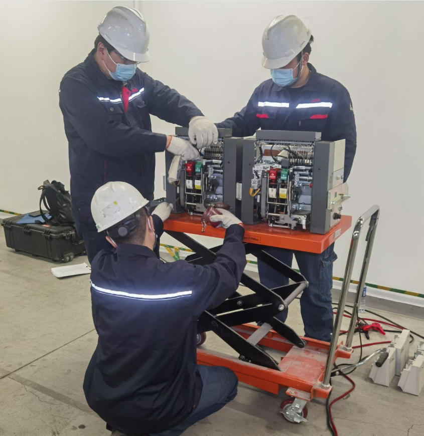
Vacuum Circuit Breaker Safety Inspection Procedures
Strong vacuum circuit breaker safety inspection procedures begin with disciplined routine observation. Not every hazard requires a laboratory test to detect it.
For sites with staffed operation, inspection should be carried out daily. For unstaffed sites, inspection should be performed at least twice per month.
Each inspection should focus on the following points:
Open/close position indication is correct and consistent with remote signal.
Insulators are clean, intact, and free from cracking, discharge traces, or contamination buildup.
Vacuum interrupter exterior shows no abnormal darkening, damage, looseness, or structural concern.
Grounding connections are intact and secure.
Primary leads and terminals show no overheating, discoloration, or smell of insulation distress.
Mechanism condition is normal, with no abnormal sound, vibration, or obstruction.
Stored-energy status and control circuit supply are normal.
These checks sound basic, but many failures occur because basic inspections were skipped repeatedly in the belief that the breaker was “sealed” and therefore self-sufficient.
Special Inspection Conditions That Should Never Be Skipped
Routine inspection intervals are not enough by themselves. Certain operating conditions require enhanced inspection.
The first is within 72 hours after energization of a newly commissioned breaker. This period often exposes installation defects, loose connections, travel errors, or mechanism issues that were not obvious during workshop testing.
Another is the night dark-room inspection. With lights reduced or switched off under controlled conditions, technicians can sometimes detect corona, discharge, or abnormal luminous effects that are difficult to see in daylight.
Additional special inspections should be made:
After thunderstorms or lightning activity
After sudden weather changes
During high temperature periods
During peak load operation
After short-circuit interruption or other abnormal switching duty
These conditions are when insulation stress, thermal stress, and mechanical weaknesses are most likely to reveal themselves.
Routine Maintenance Actions That Improve Reliability
Reliable breaker service depends on practical maintenance, not just testing paperwork.
Routine work should include cleaning de-energized components, especially insulation surfaces and mechanism areas where dust, conductive contamination, or moisture-retaining deposits can accumulate.
The drive mechanism should be inspected for wear, looseness, corrosion, and smooth operation. Lubrication must follow the equipment manual. Over-lubrication is not harmless; it can attract dirt and impair movement.
Where applicable, teams should check oil level, gas pressure, hydraulic pressure, or auxiliary system condition in associated equipment. Heater operation should also be confirmed where anti-condensation heating is installed.
Stored-energy devices, charging motors, closing coils, trip coils, auxiliary contacts, and control circuit health must all be verified.
In short, proper routine maintenance is the foundation of all effective preventive maintenance steps for vacuum circuit breakers.
Operating Rules That Prevent Human Error
Many breaker incidents are triggered or worsened by operating mistakes.
Before operation, personnel should verify control power availability, stored-energy status, and mechanism readiness. If any essential condition is missing, operation should not proceed casually.
It is strictly prohibited to use a manual lever to force close a live breaker under energized conditions. This is not just bad practice. It is a serious safety risk that can lead to incomplete closing, contact damage, arc fault, or personal injury.
If a pressure abnormality or interlock condition has blocked operation, personnel must never bypass or forcibly release the interlock simply to restore service quickly. Interlocks exist because continued operation would be unsafe.
Disciplined operation is a major part of hazard prevention. A technically healthy breaker can still fail in the hands of poor operating practice.
Fault Conditions That Require Immediate Outage Request
Some conditions are not “monitor and wait” issues. They require immediate application for outage and isolation.
Typical urgent conditions include:
Severe oil loss in related switching equipment
Sudden collapse of SF₆ gas pressure in associated apparatus
Vacuum interrupter damage accompanied by abnormal sound or visible defect
Hydraulic pressure falling to zero in applicable operating mechanisms
Persistent abnormal overheating that indicates dangerous contact or connection deterioration
Failure of withstand or characteristic testing that confirms loss of required performance
Delaying outage under these conditions usually increases repair scope and system risk. Fast isolation often turns a major event into a controlled maintenance intervention.
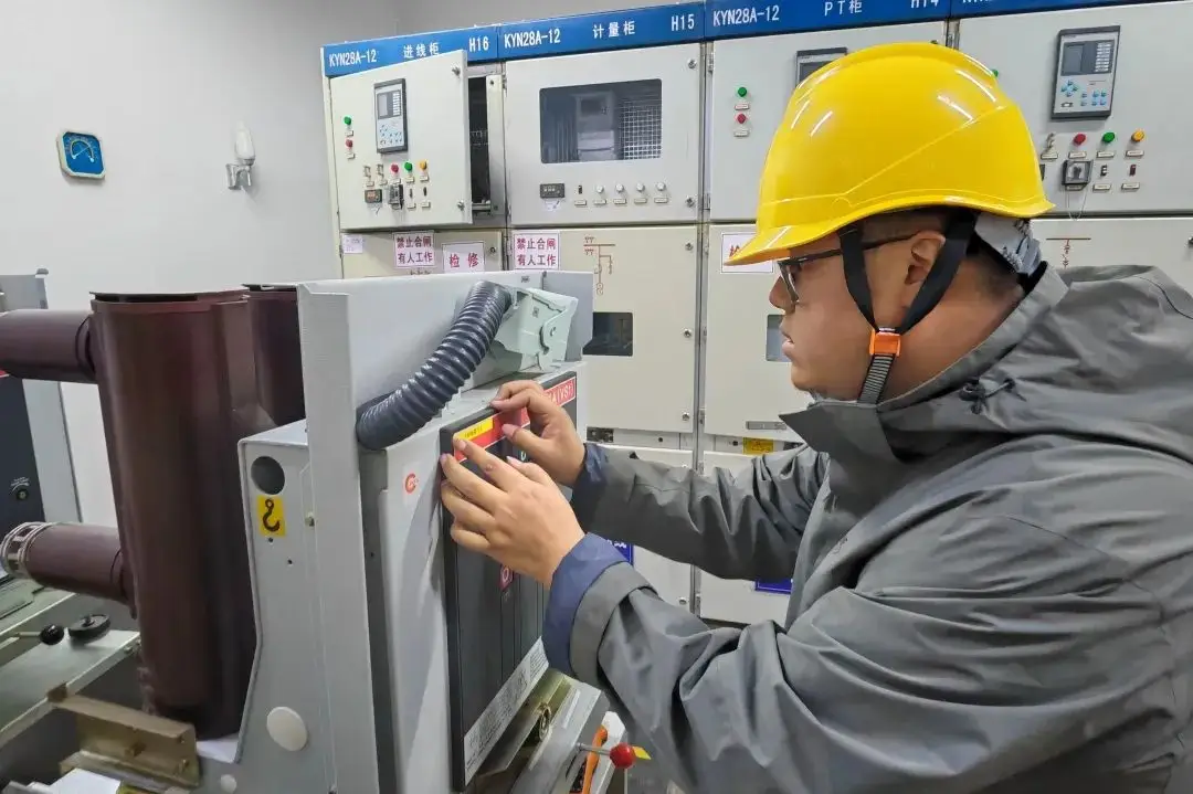
Real-World Data and Examples of Hidden Hazards in Medium-Voltage Switchgear
To keep this discussion practical, consider three field-style examples drawn from common maintenance scenarios.
Case 1: Capacitor bank restrike event. A 10 kV capacitor feeder experienced repeated switching transients after maintenance. The breaker itself seemed operational, but downstream protective devices began nuisance action.
Investigation found no effective surge arresters near the switching point, and travel traces showed excessive rebound. After adding suitable overvoltage protection and correcting the mechanism, the repeated disturbance stopped.
Case 2: Stored breaker fails commissioning withstand test. A spare breaker stored for nearly two years passed visual inspection and insulation resistance checks, but failed initial power-frequency withstand testing. After voltage conditioning and repeated preparation, performance improved, but one interrupter remained below requirement and had to be replaced.
The lesson was simple: storage time matters, and “unused” does not mean “ready.”
Case 3: Overheating traced to contact wear and poor adjustment. During summer peak load, thermal imaging found one phase of a feeder breaker running significantly hotter than the others. Loop resistance was elevated, contact wear was near the replacement threshold, and overtravel setting had drifted from the original value after prior maintenance.
The breaker still opened and closed. But without thermal inspection and resistance testing, it would likely have remained in service until a much more serious failure occurred.
These are typical examples of hidden hazards in medium voltage switchgear. They do not always announce themselves dramatically at first. They emerge through trend data, disciplined inspection, and respect for mechanical and electrical limits.
Recommended Inspection Frequency for Vacuum Circuit Breaker Maintenance
| Inspection Item | Recommended Interval | Acceptable Range / Condition | Warning Sign | Required Action |
|---|---|---|---|---|
| Staffed-site routine patrol | Daily | Normal indication, no abnormal sound or odor | Position mismatch, unusual sound, visible defect | Immediate investigation and defect logging |
| Unstaffed-site inspection | At least 2 times per month | Stable operation, no contamination or overheating | Thermal abnormality, contamination, loose parts | Schedule corrective maintenance |
| Newly energized breaker check | Within the first 72 hours | Stable operation after commissioning | Mechanism irregularity, loose connection | Re-test and tighten/adjust as needed |
| Power-frequency withstand test | About every 3 years | Pass specified test value | Failed dielectric test | Condition or replace interrupter |
| Opening/closing speed test | Before service and during major maintenance | Within specified benchmark | Speed drift or out-of-range result | Adjust mechanism, inspect springs/linkage |
| Contact wear measurement | At installation and each major overhaul | Below replacement threshold | Wear approaching 3 mm | Plan interrupter replacement |
| Thermal imaging of terminals/leads | During high load periods | No abnormal phase temperature difference | Hotspot or rising trend | Check contact pressure and resistance |
Critical Test Values and Replacement Limits
| Parameter | Reference Value | Application Note | Warning Threshold | Action |
|---|---|---|---|---|
| Vacuum level in interrupter | 10⁻⁴ to 10⁻⁶ Pa | Required for dielectric and interrupting performance | Vacuum degradation suspected or test failure | Perform integrity verification; replace if needed |
| Power-frequency withstand test | 42 kV, approximately every 3 years | Typical 10 kV class maintenance reference | Fails after conditioning | Replace interrupter |
| Contact overtravel | About 3 mm | Adjust strictly per manufacturer instructions | Too low or too high | Re-adjust and inspect spring condition |
| Contact gap | About 12 mm | Typical 10 kV reference | Gap out of tolerance | Correct travel setting and verify mechanism |
| Maximum contact wear | About 3 mm | Track from installation baseline | At or above 3 mm | Replace vacuum interrupter |
| Closing speed | 0.6 ± 0.2 m/s | Measured before operation and during maintenance | Outside range or drifting trend | Inspect and adjust mechanism |
| Opening speed | 1.6 ± 0.3 m/s | Critical to interruption and rebound control | Outside range or unstable | Inspect springs, damping, linkage |
Failure Symptoms Mapped to Root Cause and Corrective Action
| Failure Symptom | Likely Root Cause | How It Appears in Service | Corrective Action |
|---|---|---|---|
| Arc color turns dark red; shield darkens | Vacuum deterioration | Visual abnormality in glass-envelope interrupter | Perform vacuum integrity and withstand testing; replace if required |
| High loop resistance | Contact wear, low pressure, oxidation, loose conductive path | Heating, phase imbalance, poor conduction | Measure wear, adjust pressure, repair connection, replace interrupter if needed |
| Excessive rebound | Improper speed, worn mechanism, poor adjustment | Impact noise, contact damage, unstable operation | Measure speed/travel, repair mechanism, control rebound source |
| Terminal or lead overheating | Loose connection, worn contacts, insufficient pressure | Infrared hotspot, odor, discoloration | Tighten, test resistance, inspect internal wear and travel |
| Abnormal opening/closing speed | Spring fatigue, lubrication failure, linkage defect | Slow or harsh operation, increased vibration | Re-test mechanism, lubricate correctly, replace worn parts |
| Failed dielectric test | Vacuum loss, storage degradation, interrupter defect | Cannot pass commissioning or periodic withstand test | Condition interrupter; replace if still below standard |
| Abnormal sound during operation | Mechanism wear, misalignment, structural damage | New metallic knock, scraping, unstable latch sound | Remove from critical duty and inspect mechanism thoroughly |
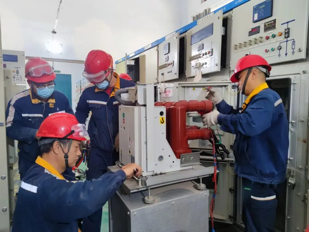
Proof Points: Why Preventive Maintenance Steps for Vacuum Circuit Breakers Work
Preventive maintenance works because vacuum circuit breaker failure is usually progressive, not instantaneous.
Manufacturers build vacuum breakers with specific mechanical tolerances and dielectric assumptions. Once service conditions move outside those tolerances, degradation accelerates.
Utility maintenance standards around the world increasingly emphasize trend-based inspection rather than one-time visual review alone. That means keeping historical records of operating speed, contact wear, loop resistance, dielectric test results, operation count, and thermal behavior.
This approach is effective because trends reveal deterioration earlier than operator complaints do.
For example, a breaker may still pass functional operation tests while speed begins drifting, contact resistance slowly rises, and thermal imbalance becomes visible under load. None of those signs alone may trigger an outage, but together they identify a clear maintenance window.
Another proof point is reduced secondary damage. When a worn or unstable breaker is corrected early, the site avoids collateral impact on cables, capacitor banks, transformers, bus insulation, and associated protection devices.
In real maintenance economics, this matters. Replacing one interrupter assembly during planned downtime is far cheaper than recovering from a switchgear compartment failure, fire event, or unexpected feeder shutdown.
This is the practical value of a disciplined vacuum circuit breaker maintenance checklist: not just keeping the breaker healthy, but protecting the whole distribution system around it.
Annual Technical Supervision Checklist
Annual technical supervision should be formal, documented, and reviewed by responsible engineering personnel.
The yearly checklist should include:
Short-circuit capacity verification to confirm system fault level still matches breaker rating
Operation count statistics to identify high-duty breakers that may need earlier overhaul
Insulation testing according to standard maintenance intervals
Mechanical and characteristic testing, including speed, travel, and timing where applicable
Review of anti-accident measures and implementation status
Defect trend review for resistance, wear, temperature rise, or repeated alarms
This annual review is where maintenance shifts from reactive work to asset management.
FAQ
What are the most common vacuum interrupter failure warning signs?
The most common warning signs include arc-color change, shield darkening, abnormal operating sound, overheating of leads or terminals, increased contact or loop resistance, and failed dielectric or withstand tests. Mechanism abnormalities such as unstable speed, excessive rebound, or irregular travel are also strong indicators that the interrupter or operating mechanism requires immediate evaluation.
How often should a vacuum circuit breaker be inspected?
For staffed sites, routine inspection should typically be performed daily. For unstaffed sites, inspection should be carried out at least twice per month, with additional checks after commissioning, storms, sudden weather changes, peak heat, peak load, or any abnormal switching event.
What is the acceptable vacuum level inside a vacuum interrupter?
The typical vacuum range is about 10⁻⁴ to 10⁻⁶ Pa. If vacuum integrity declines below this effective range, the interrupter’s dielectric strength and current-interrupting performance are reduced, increasing the risk of failed switching duty or insulation breakdown.
When should a vacuum interrupter be replaced?
A vacuum interrupter should be replaced when contact wear reaches about 3 mm, when withstand performance remains below standard after conditioning, or when mechanical damage, leakage, bellows failure, or other structural defects are detected. Replacement is also necessary if testing confirms unacceptable vacuum deterioration.
Why is overvoltage protection necessary for vacuum circuit breakers?
Overvoltage protection is necessary because switching small inductive current, such as transformer magnetizing current, can create current-chopping overvoltage, while switching capacitor banks can create restrike overvoltage. These transients can stress insulation and damage connected equipment, so metal-oxide surge arresters or RC protection are often required.
What opening and closing speeds are considered normal?
Typical reference values are about 0.6 ± 0.2 m/s for closing speed and 1.6 ± 0.3 m/s for opening speed, depending on the breaker design. Poor speed control can increase wear, vibration, rebound, and interruption instability, so baseline and trend records are important.
Can rebound really damage the vacuum interrupter and connected equipment?
Yes. Excessive rebound can burn or weld contacts, crack bellows and cause leakage, deform conductive rods, and increase vibration stress. In capacitor switching duty, rebound can also contribute to damaging transients that affect the capacitor bank and associated equipment.
Final Safety Takeaway
A vacuum circuit breaker becomes dangerous when people stop treating it as a precision device.
The most effective defense against hidden failure is not guesswork. It is standardized installation, verified vacuum condition, precise control of contact and mechanism parameters, disciplined inspection, and timely replacement before limits are exceeded.
If your maintenance program already includes trend records, withstand testing, wear tracking, speed measurement, surge protection review, and special inspections after critical events, you are reducing risk in the right way.
If it doesn't, a hidden hazard may already be developing inside your switchgear lineup.
CTA
Don’t wait for the next outage, restrike event, or overheating alarm to expose a preventable defect.
Audit your current vacuum circuit breaker safety inspection procedures, update your maintenance checklist, verify your breaker test records, and schedule a professional assessment now.
If you are evaluating new medium-voltage switching solutions or need technical support for safer breaker operation, contact a qualified engineering partner today to ensure your system is ready before the next fault tests it for real.