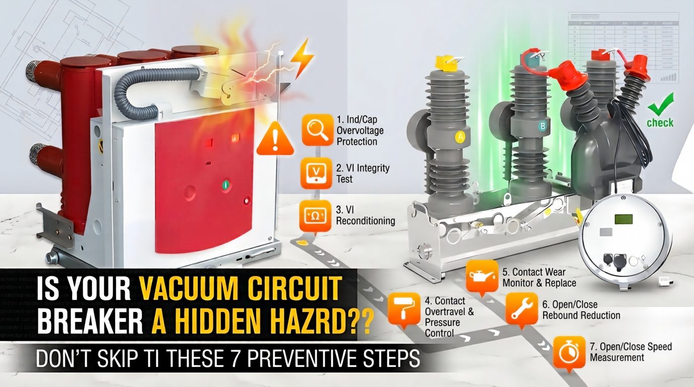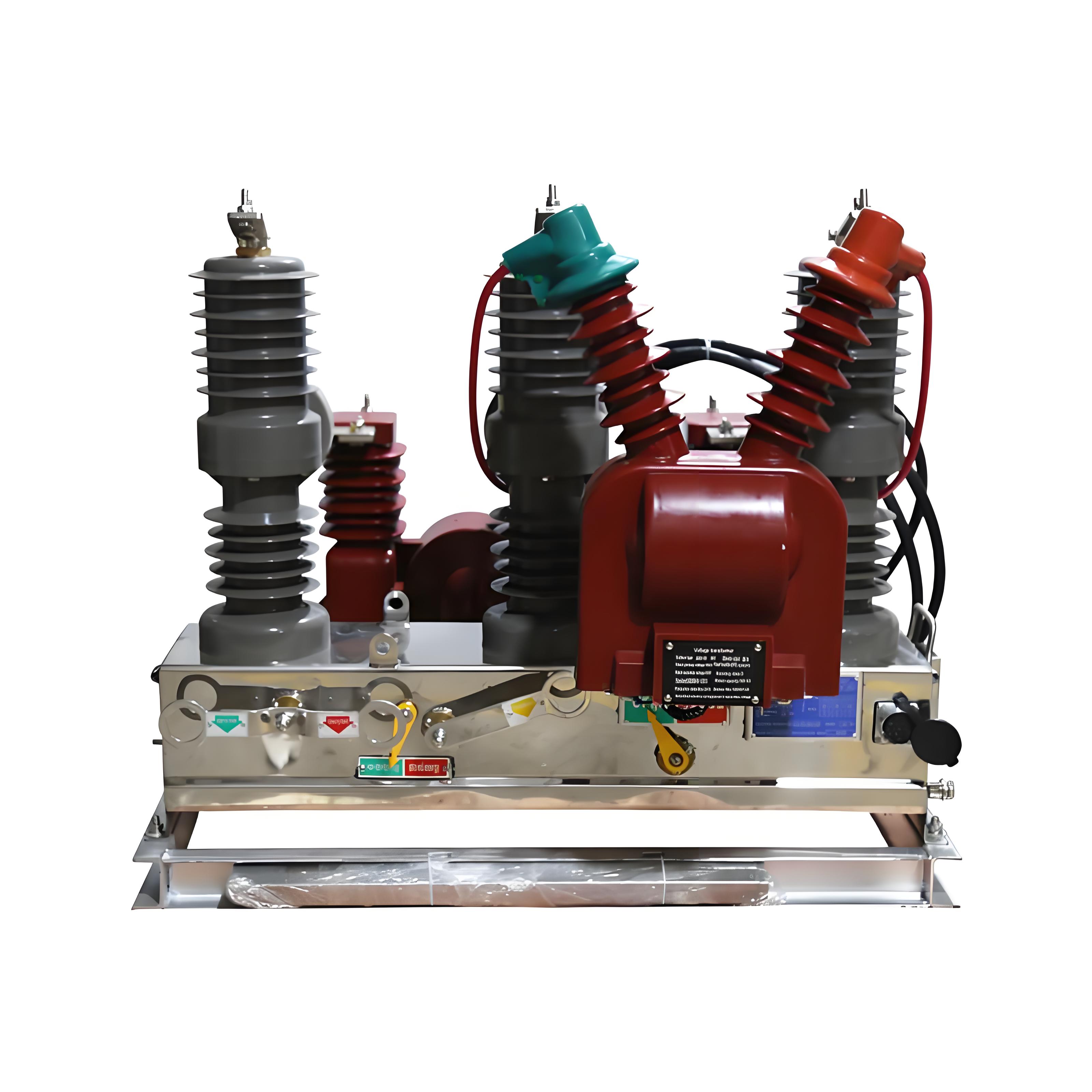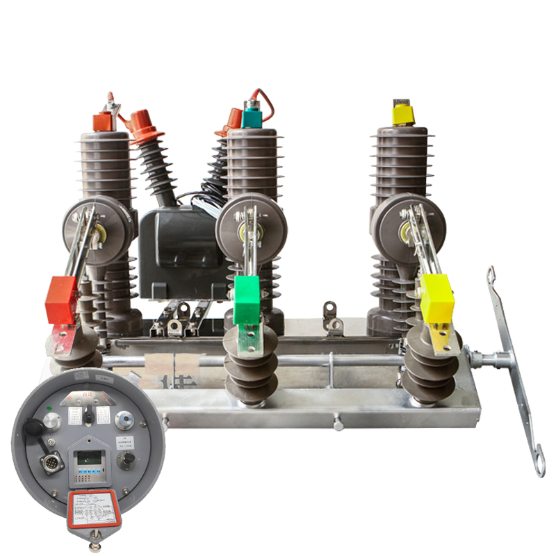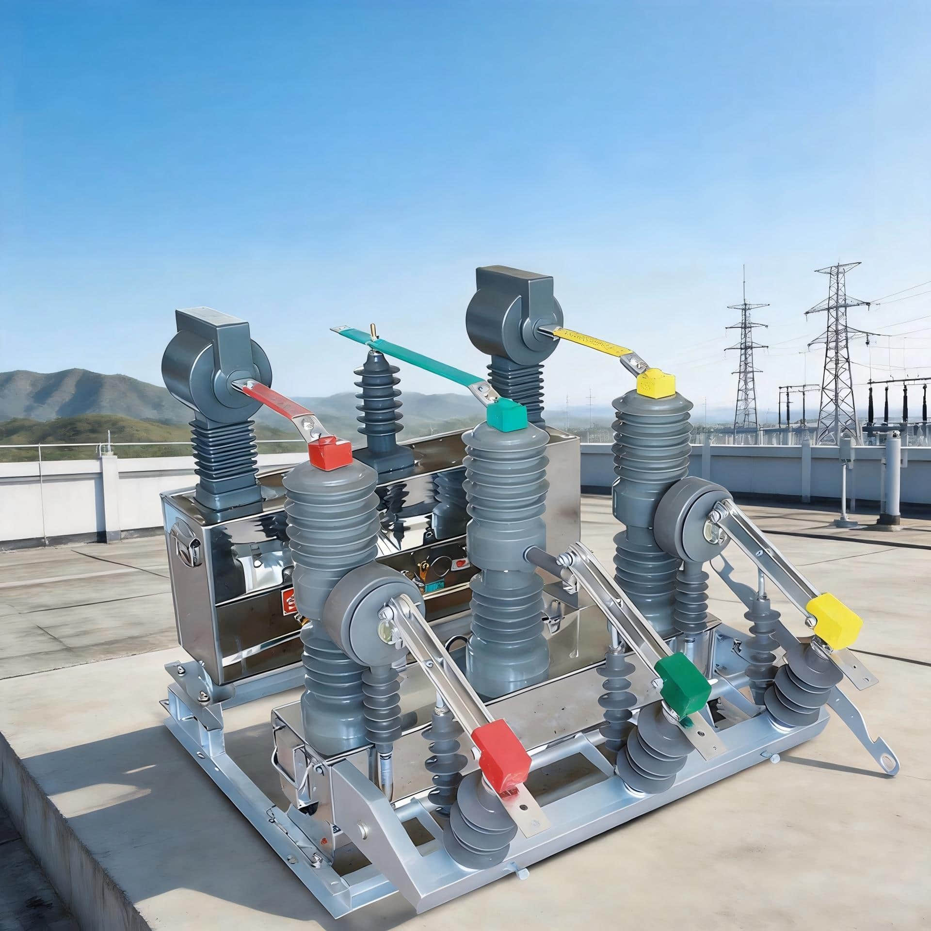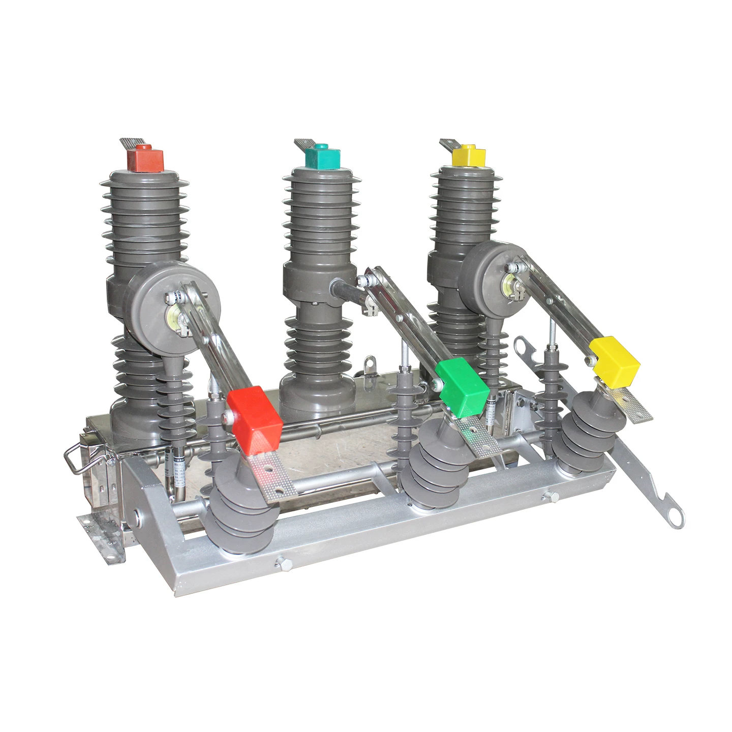
For years, conventional maintenance logic treated the vacuum interrupter in a vacuum circuit breaker as a largely “non-disassembly” component. If the operating mechanism spring, linkage, and timing still tested within limits, many teams assumed the breaker was healthy enough to stay in service.
Field data tells a different story. In a large share of early overhauls, the real trigger is not spring fatigue, but localized arc residence, uneven contact erosion, and drifting contact resistance.
That distinction matters because it changes the entire maintenance strategy. If the root problem is electrical and thermal concentration at the contact face, then simply using a harder contact alloy will not reliably extend service life.
The deeper engineering answer is to couple magnetic field structure design with contact microstructure. In other words, arc-control geometry and alloy design must work together to keep the arc moving, prevent it from pinning in one spot, and slow the rate of irreversible surface damage.
This is the real lever behind extending maintenance intervals with vacuum breaker contacts. It is also one of the most overlooked drivers of total cost of ownership for medium voltage switchgear.
In practice, buyers often compare breakers only by rated short-circuit current and total interruption count. But maintenance managers know the more painful truth: a breaker can remain below its nominal operation limit and still become an early maintenance problem because one area of the contact surface has been repeatedly overheated, cratered, and rebuilt by metal splash.
Once that happens, contact resistance starts to drift. Temperature rise becomes harder to control. Infrared scans turn from routine verification into warning signs. Planned maintenance windows get pulled forward. In the worst cases, outages become forced rather than scheduled.
This article explains why that happens, how AMF and RMF contact structures address it, why vacuum circuit breaker contact material selection is a lifecycle tradeoff rather than a simple “more chromium is better” rule, and how to choose the best contact system based on actual duty profile.
Why Vacuum Circuit Breakers Are Repaired Early Even When Springs Still Test Good
In many substations and industrial switch rooms, maintenance teams perform mechanism inspections and find the mechanical side of the breaker in acceptable condition. Spring charging is normal. Opening and closing timing remain within tolerance. Yet the unit is still flagged for interrupter inspection or replacement earlier than expected.
The reason is usually visible only when you look at the contact condition trend, not just the mechanism. Localized arc erosion produces a much faster deterioration path than many maintenance plans assume.
During interruption, the vacuum arc does not always distribute itself evenly across the contact face. If arc motion is weak or unstable, the arc can dwell too long at one location. That creates a fixed hot spot with repeated high-energy bombardment.
From there, the damage sequence is familiar to experienced field engineers:
surface melting at a local point,
crater formation,
metal vapor redeposition and splash,
roughening of the contact surface,
contact pressure acting on an increasingly non-uniform interface,
progressive contact resistance drift.
The breaker may still operate mechanically. But electrically, it is moving toward unstable long-term service.
This is why early maintenance in a vacuum ckt breaker often appears “premature” if judged only by mechanical parts. The real wear-out mechanism is frequently thermal-electrical, not spring-based.
Several utility and industrial maintenance teams report the same operational pattern: after multiple fault interruptions or repeated switching under demanding conditions, some breakers show hot spot development well before the mechanism approaches end-of-life. Infrared inspections reveal one pole running hotter. Micro-ohm testing shows a gradual but persistent increase in contact resistance. At that point, continuing operation becomes a risk decision rather than a routine maintenance choice.
The Real TCO Problem in a Vacuum Ckt Breaker: Fixed Arc Spots, Uneven Erosion, and Forced Outages
The total cost problem does not begin when a contact is fully consumed. It begins much earlier, when arc energy is repeatedly concentrated on the same region of the contact.
That concentration creates non-uniform erosion. Non-uniform erosion is far more damaging to lifecycle economics than uniform wear.
Why? Because uniform wear is predictable. It can be planned for. It usually allows the breaker to maintain stable resistance and thermal performance over a longer inspection interval.
Non-uniform wear is different. It creates deep local pits and raised splash deposits. The interface becomes topographically unstable. Real contact area shrinks even when nominal mechanical force stays unchanged.
That leads to a chain of operational problems:
contact resistance rises,
temperature rise increases,
inspection frequency must be increased,
outage scheduling becomes more frequent,
vacuum interrupter replacement may be advanced.
This is the maintenance pain point many brochures skip. A manufacturer may advertise a strong short-circuit interruption rating or a certain number of breaking operations. But if arc motion is not well controlled, the breaker can still become expensive in service because one location on the contact has absorbed a disproportionate share of the thermal load.
Put simply, the best contact system does not merely survive interruption. It spreads the arc energy so that a destructive single-point hot spot does not dominate the maintenance profile.
That is why magnetic field structure is not just about ultimate breaking capacity. It is a reliability tool. It transforms concentrated damage into distributed, manageable wear.
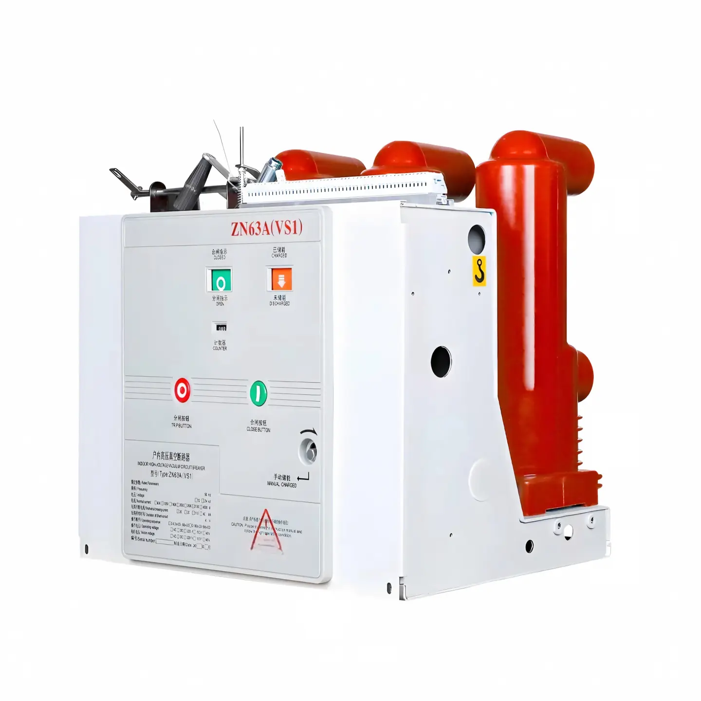
How Contact Design Extends Maintenance Intervals in a Vacuum Circuit Breaker
When engineers talk about contact design in a vacuum circuit breaker, the discussion is often reduced to rated performance. That is too narrow.
In real maintenance economics, the contact geometry is one of the most important levers for low-maintenance vacuum interrupter design. Its job is to influence the arc path, distribute current density, reduce fixed hot spots, and stabilize long-term contact resistance.
The principle is straightforward. If the arc remains fixed, one point gets punished repeatedly. If the arc is driven to move, the thermal and erosion load is spread across a larger area.
That larger-area load distribution produces three practical benefits:
shallower local erosion,
flatter wear patterns,
slower resistance drift over time.
For operators, those three benefits translate into longer stable intervals between intrusive inspections and a lower chance of surprise heating alarms.
AMF vs RMF Contact Design: Which Arc Control Method Fits Which Duty
The two most commonly discussed arc-control approaches are axial magnetic field (AMF) contacts and radial magnetic field (RMF) contacts, often realized through spiral-slot structures.
They are not interchangeable in all duty profiles. Each has strengths that become more or less valuable depending on fault frequency, current severity, and maintenance priorities.
AMF contacts create an axial magnetic field that helps distribute the vacuum arc over the contact surface. They are particularly effective in high fault-duty applications because they promote diffuse arc behavior and support stable interruption at demanding short-circuit levels.
RMF contacts, especially spiral-slot designs, generate a radial magnetic field component that drives the arc to rotate around the contact face. Their major value is not merely increased interruption capability, but continuous arc motion that prevents the arc from burning at one fixed point.
From a maintenance strategy perspective:
AMF is often preferred where fault duty is frequent and severe, and where keeping erosion uniformly distributed is essential for long maintenance windows.
RMF spiral-slot designs are highly effective where rotational arc motion can sharply reduce local hotspot formation and help preserve resistance stability after repeated events.
In heavy-duty industrial feeders, mining distribution systems, and fault-prone networks, the best solution may be a premium arc-control structure paired with an optimized CuCr microstructure. In lower-fault applications, the optimal balance can be different.
Why Spiral-Slot RMF Contacts Reduce Local Hotspots
Spiral-slot RMF contacts are often described in terms of current interruption performance. But their maintenance value deserves equal attention.
The spiral slot is fundamentally an arc motion management feature. It is designed to keep the arc moving across the contact face instead of allowing it to lock onto one location.
That motion matters because arc residence time at a local point is one of the biggest predictors of crater depth and post-arc surface instability. If the arc rotates continuously, the heat load is divided over a wider area. The result is lower peak surface temperature at any one point and less severe localized melting.
This is the practical meaning of “spreading the arc.” It is not abstract theory. It is how contact design slows the progression from normal wear to resistance drift and maintenance-triggering overheating.
Engineers who have cut open failed interrupters know the pattern well. Fixed-point arc behavior leaves deep, obvious damage signatures. Rotating arc behavior produces a much flatter wear map.
Test Data: How Spiral-Slot Geometry Improves Arc Motion and Reduces Erosion
Field observations are important, but they are even more useful when backed by geometry-linked test results. For spiral-slot RMF contacts, one test configuration stands out: slot depth 4.5 mm and slot width 6 mm.
Under that geometry, testing showed that arc-driving force increased by 35%, while current density uniformity improved by 25%.
These are not cosmetic gains. They directly affect how thermal stress is distributed during interruption.
Better arc-driving force means the arc is less likely to stall at one location. Better current density uniformity means less chance of localized overloading on the contact face. Together, those effects substantially reduce local erosion depth after a short-circuit interruption and help maintain contact resistance stability over the long term.
Spiral-Slot Contact Geometry vs Arc-Driving Performance
| Parameter | Baseline Contact | Optimized Spiral-Slot RMF Contact | Observed Effect |
|---|---|---|---|
| Slot Depth | Not optimized | 4.5 mm | Improved magnetic arc-driving action |
| Slot Width | Not optimized | 6 mm | More stable rotational arc path |
| Arc-Driving Force | Reference level | +35% | Reduced arc pinning tendency |
| Current Density Uniformity | Reference level | +25% | Lower local thermal concentration |
In practical maintenance terms, this means fewer severe pits after individual fault interruptions and a longer period before resistance growth becomes unacceptable.
Single Short-Circuit Interruption Results Before and After Arc Distribution Optimization
| Metric After Single Short-Circuit Interruption | Before Arc Distribution Optimization | After Arc Distribution Optimization | Maintenance Impact |
|---|---|---|---|
| Local Erosion Depth | Deep localized crater | Substantially reduced local depth | Lower risk of early resistance drift |
| Wear Pattern | Highly uneven, fixed-point damage | Flatter and more distributed wear | Longer stable inspection interval |
| Metal Splash Deposition | Pronounced buildup near hotspot | Reduced concentrated redeposition | Better contact interface stability |
| Contact Resistance Trend | More likely to drift upward quickly | More stable over time | Less forced maintenance |
This is where the maintenance story becomes concrete. A contact that controls arc motion effectively does not just “look better” after a test. It preserves the operating window in which resistance remains predictable, temperature rise remains manageable, and outages can stay scheduled instead of reactive.
Why Higher Hardness Alone Does Not Lower Total Cost of Ownership
A common industry shortcut is to assume that a harder contact material will automatically last longer. That assumption is incomplete.
Hardness can improve resistance to deformation and some forms of wear. But if the arc remains pinned to one location, even a hard surface will still be exposed to repeated, concentrated thermal attack.
Arc erosion is not governed by hardness alone. It is governed by where the arc goes, how long it stays there, how heat spreads, how the microstructure responds to melting and resolidification, and how the surface topography evolves after each event.
Without proper magnetic field design, a very hard contact can still develop:
deep local craters,
rough welded-recast regions,
unstable current constriction zones,
accelerated contact resistance increase.
That is why the best lifecycle result comes from a combined design logic:
magnetic structure to keep the arc moving,
microstructure optimized to resist destructive melting patterns,
alloy selection matched to actual load and fault duty.
In short, you cannot buy your way to lower maintenance with hardness alone. You need arc control plus material science.
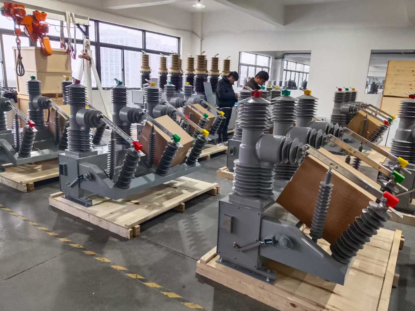
Vacuum Circuit Breaker Contact Material Selection: CuCr25 vs CuCr50 vs Fine-Grain CuCr
Vacuum circuit breaker contact material selection is one of the most misunderstood parts of interrupter specification. Too often, selection is reduced to a simplistic ranking where higher chromium means longer life and therefore better value.
Real engineering is not that simple.
CuCr contact systems involve a classic tradeoff between:
electrical conductivity,
arc erosion resistance,
anti-welding performance,
continuous operating loss,
maintenance interval potential.
The right alloy depends on the site. A breaker installed on a fault-prone mine feeder should not be optimized the same way as one feeding a stable distribution branch that rarely sees short-circuit stress.
CuCr25: Lower Losses for Low-Fault Distribution Networks
CuCr25 offers relatively better conductivity because of its lower chromium content. That makes it attractive for sites where the breaker spends most of its life carrying rated load and rarely experiences major fault interruption duty.
In those scenarios, continuous operating losses matter. Lower contact resistance and better conductivity can reduce Joule heating cost over years or decades of service.
For standard distribution networks with low fault incidence, CuCr25 is often the economically correct answer. It provides sufficient performance without imposing unnecessary running-loss penalties.
This is especially relevant in utility or commercial distribution systems where operating hours are long, load is steady, and major short-circuit interruptions are infrequent.
CuCr50: Stronger Erosion Resistance but Higher Running Losses
CuCr50 contains more chromium, which improves anti-erosion capability and resistance to contact welding under severe arc conditions. That is why it is often favored in demanding interruption environments.
However, this higher chromium content comes with a cost: lower conductivity compared with CuCr25. Over a long service life, that can translate into greater resistive loss and more cumulative heating energy.
This is the industry misconception that causes many poor purchasing decisions. Choosing high-chromium CuCr50 blindly does not automatically produce the lowest lifecycle cost.
If the site rarely experiences fault interruption, the added erosion resistance may never repay its higher long-term operating loss. In such a case, the buyer pays more upfront and may also pay more in energy over time.
Fine-Grain CuCr: The Key Materials Breakthrough for Low Maintenance Vacuum Interrupter Design
The most important material development in recent years is not just a change in composition, but a change in microstructure.
Testing reported in materials research literature shows that for the same nominal CuCr50 composition, a fine-grain process can produce much better arc-damage behavior than conventional coarse-grain material.
The reason is microstructural. When the chromium phase is refined into smaller, more uniformly distributed grains, the cathode spots formed during arcing become smaller and more evenly distributed as well. After arcing, the surface tends to remain flatter, with fewer large molten craters.
That matters enormously for maintenance. A flatter post-arc surface means the contact interface degrades more slowly. Resistance drift is delayed. Inspection intervals can be extended with more confidence.
You can think of the refined chromium phase as countless tiny high-temperature micro-skeletons. When the copper matrix melts under arc energy, those micro-skeletons help suppress large-scale splash and prevent the formation of highly irregular, irreversible topography.
In practical terms, fine-grain CuCr improves contact erosion resistance in vacuum circuit breakers not merely through chemistry, but through better control of how the surface survives and recovers from arc attack.
Materials Science Proof: Why Fine-Grain CuCr Improves Contact Erosion Resistance in Vacuum Circuit Breakers
Materials science gives a clear explanation for why fine-grain CuCr performs better than conventional coarse-grain CuCr of the same composition.
In coarse-grain structures, the chromium-rich phase is less uniformly distributed. Under arc bombardment, localized melting and thermal stress can produce larger unstable molten pools, more pronounced splash, and deeper crater formation.
In fine-grain structures, the chromium phase acts more uniformly throughout the contact. This creates several beneficial effects:
smaller cathode spots,
more even energy distribution,
reduced large-area molten flow,
suppressed metal splash,
smoother post-arc surfaces.
The result is not just better laboratory performance. It directly influences the shape of the maintenance curve in service.
A smoother surface after repeated interruptions means:
more stable real contact area,
slower increase in constriction resistance,
lower probability of abnormal hot spots,
longer intervals before intervention is needed.
For operators focused on extending maintenance intervals with vacuum breaker contacts, this is exactly the kind of improvement that matters.
CuCr Contact Material Comparison for Maintenance Interval and Lifecycle Cost
| Contact Material | Conductivity | Arc Erosion Resistance | Anti-Weld Behavior | Continuous Operating Loss | Maintenance Interval Potential | Best-Fit Application |
|---|---|---|---|---|---|---|
| CuCr25 | Higher | Moderate | Moderate | Lower | Good in low-fault duty | Standard distribution with rare short-circuit events |
| Conventional CuCr50 | Lower than CuCr25 | High | Strong | Higher | Good in high-fault duty, but depends on surface evolution | Heavy-duty interruption environments |
| Fine-Grain CuCr50 | Lower than CuCr25 | Very high | Strong | Higher | Highest where arc control and long interval strategy are critical | Industrial, mining, and high-consequence outage applications |
Total Cost of Ownership for Medium Voltage Switchgear: The Cost Model Most Buyers Miss
One of the biggest purchasing mistakes in medium-voltage equipment is to focus on breaker purchase price while underestimating the financial impact of maintenance interruption and long-term electrical loss.
The proper model for total cost of ownership for medium-voltage switchgear must include at least three categories:
direct maintenance cost,
continuous energy loss cost,
secondary failure risk cost.
Once contact deterioration is understood as a dominant driver of early intervention, these cost buckets become much easier to quantify realistically.
Direct Cost Bucket: Inspection, Outage Labor, and Vacuum Interrupter Replacement
These are the visible costs buyers usually understand first.
planned shutdown coordination,
maintenance labor,
switchgear isolation and safety preparation,
micro-ohm measurement and diagnostic testing,
replacement interrupters or spare poles,
recommissioning and return-to-service work.
In industrial facilities, the cost of outage support can exceed the cost of the breaker component itself. If a production line, ventilation system, crusher train, or process feeder must be stopped for contact-related maintenance, the labor and operational impact escalate quickly.
That is why a premium contact design that extends preventive maintenance from 2 to 3 years out to 6 to 8 years can be financially compelling even if the initial purchase price is higher.
Hidden Cost Bucket: Energy Losses from Higher Resistance and Poorer Conductivity
This is the cost many “long-life” claims fail to account for.
Higher chromium contact systems generally provide stronger arc resistance, but they can also impose higher long-term electrical losses due to reduced conductivity. Over decades of service, that energy penalty accumulates.
For low-fault breakers that spend nearly all their life carrying load rather than interrupting faults, the electricity cost associated with slightly higher resistive loss can outweigh the theoretical benefit of extra erosion resistance that is rarely used.
This is why CuCr25 often makes more economic sense in standard distribution networks. Lower loss over a long duration can beat excess short-circuit ruggedness that the application does not need.
Hidden Risk Cost Bucket: Secondary Failure Triggered by Contact Deterioration
This is the cost bucket that experienced operators respect the most, because it causes the worst surprises.
When contacts deteriorate through local melting, uneven erosion, or micro-welding, the consequences are not limited to the contact itself. The switching behavior of the breaker can change.
One underappreciated risk is chopping current drift. As contact condition degrades, the breaker’s interruption behavior may shift. That can increase switching overvoltage exposure.
The result can be secondary damage to connected equipment such as:
instrument transformers,
control transformers,
motor windings,
medium-voltage cables,
termination insulation systems.
So a well-designed contact system does more than prolong contact life. It helps reduce the probability of downstream failures and the maintenance spend of the entire distribution system.
This is where authoritative suppliers and engineering-led manufacturers distinguish themselves. A company such as Weisho Electric is most valuable when it helps customers match contact structure and alloy to actual operating duty rather than pushing a one-size-fits-all “premium” option.
Best-Fit Design by Operating Scenario
The correct contact solution depends on how the breaker is really used. Not all duty profiles justify the same contact structure or alloy package.
Below is the practical selection logic that aligns engineering with lifecycle cost.
Frequent Fault Duty: Industrial, Mining, and Heavy Distribution Systems
In industrial plants, mines, and heavy-duty distribution systems, short-circuit events or severe switching stresses are more likely. Outage consequences are also much more expensive.
In these cases, AMF plus fine-grain CuCr is usually the right priority path.
Yes, the purchase price is higher. But the total value comes from avoided maintenance and avoided disruption.
Where conventional contact systems might force preventive maintenance every 2 to 3 years, a stronger arc-control and fine-grain material package can extend that window to roughly 6 to 8 years in suitable duty conditions. The exact result depends on fault history, load level, and switching frequency, but the lifecycle trend is clear.
That means fewer planned shutdowns, fewer spare interrupters, less field labor, and lower risk of costly unplanned outages.
In a mine, one avoided unscheduled outage can easily outweigh the premium paid for a better interrupter contact system. In a continuous process plant, the avoided production loss is often the dominant economic factor.
Low-Fault, Steady-Load Duty: Standard Distribution Networks
For standard distribution applications with rare short-circuit duty and long periods of stable load carrying, the economics change.
Here, CuCr25 is often the smarter choice. It offers adequate interruption performance while keeping continuous operating losses lower.
If a buyer specifies CuCr50 in this type of application simply because it sounds more rugged, the result may actually be a higher lifecycle cost. The breaker may never use the extra anti-arc margin enough to offset the additional resistive loss over its service life.
This is why proper application analysis is more important than generic specification habits.
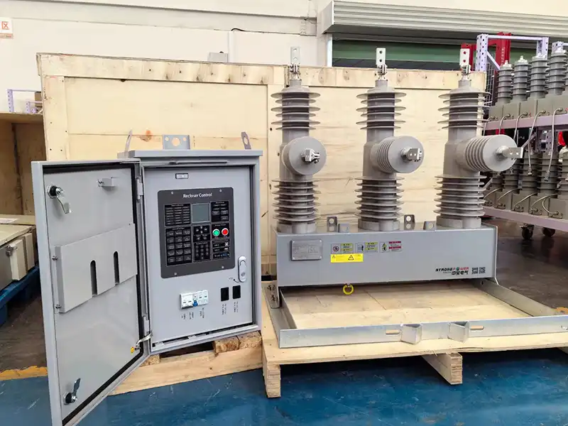
Real-World Example: When a Higher Purchase Price Lowers TCO
Consider a simplified but realistic comparison between two 12 kV feeder breakers serving an industrial processing line.
Both breakers meet the required short-circuit rating. The standard unit uses a basic contact package. The premium unit uses an advanced arc-control structure with fine-grain CuCr contact material.
The premium unit costs more on day one. But the site has a history of fault events, heavy motor loads, and expensive shutdowns for inspection. In this environment, the premium design is not over-specification. It is risk control.
Suppose the standard breaker requires intrusive maintenance every 2.5 years on average because contact resistance trend alarms trigger earlier. The premium breaker, by contrast, extends practical preventive maintenance to around 7 years under the same operating conditions.
Now add the actual cost elements:
shutdown coordination labor,
electrical crew time,
spare interrupter inventory,
production interruption exposure,
energy loss over service life.
The premium option often wins decisively, even if the CapEx delta initially looked significant.
Example LCC Comparison for Premium vs Standard Vacuum Circuit Breaker Contact Systems
| Cost / Performance Factor | Standard Contact System | Premium Arc-Control + Fine-Grain Contact System | LCC Direction |
|---|---|---|---|
| Initial Purchase Cost | Lower | Higher | Standard advantage at purchase only |
| Typical Preventive Maintenance Cycle | 2–3 years | 6–8 years | Premium strongly reduces maintenance frequency |
| Unplanned Outage Exposure | Higher due to earlier resistance drift risk | Lower due to better arc distribution and surface stability | Premium reduces risk cost |
| Spare Interrupter Use | Higher over asset life | Lower over asset life | Premium reduces replacement spend |
| Labor for Inspection / Intervention | Higher cumulative | Lower cumulative | Premium lowers service cost |
| Energy Loss Impact | Depends on alloy used | Must be evaluated carefully against conductivity | Application-specific balance required |
| Total Lifecycle Cost | Often higher in fault-prone, outage-sensitive duty | Often lower despite higher CapEx | Premium wins in high-consequence applications |
This is the kind of analysis serious buyers should request from suppliers. The question is not, “Which contact is toughest?” The better question is, “Which contact system produces the lowest lifecycle cost for my duty profile?”
How to Evaluate Extending Maintenance Intervals with Vacuum Breaker Contacts
If your goal is extending maintenance intervals with vacuum breaker contacts, you need a decision framework grounded in site reality.
Start with five questions:
1. How often does this feeder or breaker experience fault interruption duty?
2. What is the long-term load current profile?
3. How expensive is each planned outage?
4. What is the cost of one unplanned outage at this location?
5. How much secondary equipment risk can the system tolerate?
Once those answers are clear, contact structure and alloy selection becomes much more rational.
Table: Contact Selection Checklist for Vacuum Circuit Breaker Buyers
| Application Type | Fault Frequency | Load Current Profile | Target Maintenance Interval | Recommended Contact Design | Recommended Material |
|---|---|---|---|---|---|
| Mining feeder | High | Heavy and variable | Maximize interval, minimize forced outages | AMF or advanced arc-control design | Fine-grain CuCr50 |
| Industrial process line | Moderate to high | Motor-rich, consequence-sensitive | 6–8 years where feasible | AMF plus strong arc distribution features | Fine-grain CuCr50 |
| Heavy distribution substation | Moderate | Mixed duty | Extended interval with controlled risk | AMF or optimized RMF | CuCr50 or fine-grain CuCr50 based on outage economics |
| Standard utility distribution feeder | Low | Steady rated-load operation | Economical long-term service | Standard proven contact design | CuCr25 |
| Commercial building main distribution | Low | Stable load, low fault exposure | Low operating loss priority | Conservative standard design | CuCr25 |
A disciplined supplier should also help buyers verify whether the application really justifies premium contact architecture. That kind of technical honesty is a sign of engineering maturity.
When discussing a project with Weisho Electric, buyers should expect that level of application-based analysis rather than a generic recommendation disconnected from fault history and operating economics.
FAQ
What causes early maintenance in a vacuum circuit breaker if the mechanism is still healthy?
In many cases, the trigger is localized arc pinning, uneven contact erosion, and rising contact resistance rather than mechanism wear. The breaker may still pass mechanical checks, but thermal instability and resistance drift force early intervention.
Does a higher chromium CuCr contact always last longer in service?
No. CuCr50 generally offers stronger erosion resistance and anti-weld behavior, but in low-fault applications its lower conductivity can increase long-term operating losses. The best choice depends on the actual balance between fault duty and continuous load cost.
How do AMF and RMF contacts reduce maintenance frequency?
Both designs control arc motion so the arc energy is spread across the contact surface instead of being concentrated at one hotspot. That reduces localized cratering, keeps wear flatter, and slows contact resistance drift.
Why is spiral-slot geometry important in a vacuum ckt breaker contact?
Spiral-slot geometry increases arc-driving force and improves current density uniformity, which helps keep the arc rotating across the contact face. This reduces local erosion depth, prevents fixed hot spots, and stabilizes long-term contact resistance.
What is the benefit of fine-grain CuCr over conventional CuCr50?
Fine-grain CuCr improves arc erosion behavior through microstructural refinement, not just composition. The refined chromium phase supports smaller cathode spots, smoother post-arc surfaces, and slower resistance degradation than conventional coarse-grain CuCr50.
How does contact deterioration affect the rest of the switchgear system?
It can alter chopping current behavior, increase switching overvoltage risk, and trigger secondary failures in connected equipment such as transformers, cables, and insulation systems. Good contact design reduces these system-level risks, not just contact wear.
Which contact material is best for low-fault distribution applications?
CuCr25 is often the better economic choice where short-circuit events are rare and the breaker spends most of its life carrying steady load. Its better conductivity helps reduce continuous operating loss over the asset lifetime.
How should buyers calculate total cost of ownership for medium voltage switchgear?
They should include purchase cost, outage labor, spare interrupters, inspection frequency, long-term energy loss, and the risk cost of secondary equipment failures caused by deteriorating contact behavior. Looking only at initial price almost always leads to a distorted decision.
Get a Contact Design and Material Fit Assessment for Your Duty Profile
If you are specifying or replacing a vacuum circuit breaker, do not settle for a generic contact package based only on interrupting rating. The real economic question is how the breaker will age in your actual network.
Fault frequency, load profile, maintenance access, outage cost, and downstream equipment sensitivity should all shape the contact design. That is how you reduce forced outages, extend stable maintenance intervals, and lower the true lifecycle cost of the installation.
Request an application-based assessment now to identify the right combination of AMF or RMF structure, CuCr25 or CuCr50 alloy, and fine-grain contact technology for your service conditions.
Talk to a qualified engineering team today, share your duty profile, and get a practical recommendation that cuts maintenance burden instead of just adding specification cost.
The right contact design can save years of unnecessary intervention and prevent expensive secondary failures. Act before your next breaker purchase or retrofit locks in the wrong lifecycle cost curve.