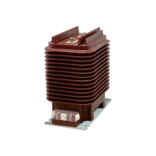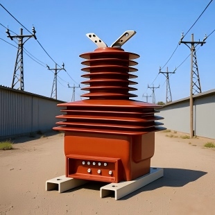
One wrong current transformer can undermine an entire power station. A mismatched CT can create billing errors, nuisance trips, false alarms, or, worst of all, protection failure during a real fault.
In generator plants, auxiliary systems, and switchyards, current transformer selection is never a minor detail. It is a core engineering decision that directly affects safety, relay performance, revenue metering, and equipment survivability.
Why Current Transformer Selection Matters in Power Stations
A CT is the link between primary power equipment and the instruments or relays that make decisions. If that link is wrong, every downstream measurement can be wrong.
In practical station design, poor CT selection can lead to under-registration of energy, unstable differential protection, overcurrent relay misoperation, and saturation during external faults. These are not theoretical risks; they are common root causes found during commissioning investigations and post-fault analysis.
For EPC contractors, utilities, and plant engineers, current transformer selection for power stations must be treated as a protection and measurement design task, not just a component purchase.
Key Inputs Before Selecting a Current Transformer
Before any ratio or class is chosen, define the operating conditions first. This prevents late-stage redesign and procurement mistakes.
System voltage class
Rated continuous current
Maximum overload current
Short-circuit current level
Installation location such as auxiliary board, generator outlet, transformer bay, or switchyard
Insulation level and BIL
Secondary burden including relay, meter, and cable load
Accuracy class
Protection purpose such as metering, differential, overcurrent, REF, or busbar protection
Number of cores
Environmental conditions such as altitude, pollution, temperature, and seismic requirements
Current Transformer Selection for Power Stations: Step-by-Step
A structured process reduces errors and makes technical specifications easier to verify. The sequence below reflects standard engineering practice across thermal, hydro, gas turbine, and combined-cycle plants.
Determine the Installation Voltage Level
The first check is location and insulation class. CT design must match the actual station voltage level, not just the nominal equipment current.
Low voltage auxiliary power: 0.66kV CT
Medium voltage generator outlet: 7.2kV / 12kV / 40.5kV CT
High voltage switchyard (step-up substation): 126kV / 252kV / 550kV CT
This distinction matters because insulation, creepage distance, impulse withstand, and mechanical construction change significantly across these voltage classes.
Identify the System Standards and Common International Voltage Classes
Many projects use equipment classes aligned with international practice rather than exact system nominal voltage. This is normal and should be clearly reflected in the CT specification.
14.4kV CT for 13.8kV grid applications
72.5kV CT for 69kV grid applications
245kV CT for 230kV grid applications
These equipment classes provide the necessary insulation margin and align with common switchgear and substation manufacturing standards.
Calculate the Required Primary Current Rating
Base the CT primary rating on the equipment full-load current and then apply a realistic margin for overload and operating variation. A CT that is too small may saturate or overheat; one that is too large may reduce metering precision at normal load.
For generators, transformers, feeders, and bus sections, calculate full-load current from rated MVA and system voltage, then compare that result with available standard CT ratios.
Select the Secondary Current
The normal choice is 1A or 5A. In modern power stations, 1A is often preferred for long cable runs because it reduces secondary burden and I²R loss.
5A secondaries still appear in legacy systems, retrofit projects, and plants where existing relays and meters are designed around 5A inputs.
Choose Metering or Protection Function
Do not assume one CT core can do everything well. Metering and protection duties often require different magnetic behavior.
Metering cores must remain accurate at normal current. Protection cores must avoid harmful saturation during faults. That is why separate cores are commonly specified in serious plant designs.
Define Accuracy Class and Burden
Power station CT accuracy class and burden should be selected together. Accuracy is not meaningful unless the actual burden is known.
Include the connected device burden plus terminal blocks, test switches, cable resistance, and a margin for future additions. Underestimating burden is one of the most frequent CT specification errors.
Check Short-Time Thermal and Dynamic Current Ratings
The CT must survive the station short-circuit duty. Verify Ith for short-time thermal current and Idyn for peak dynamic current.
As a practical rule, the CT should withstand the worst-case fault level at its exact location, whether at the generator terminals, auxiliary switchboard, transformer bay, or HV switchyard.
Verify Knee Point and Saturation Performance for Protection
Protective current transformer sizing for generators and feeders depends heavily on saturation behavior. Differential and REF relays may misoperate if the CT knee point is too low during through-fault conditions.
For protection duties, especially generator differential, transformer differential, and busbar protection, review knee point voltage, excitation current, and transient response data rather than relying only on the nominal ratio.
Current Transformer Types Used in Power Stations
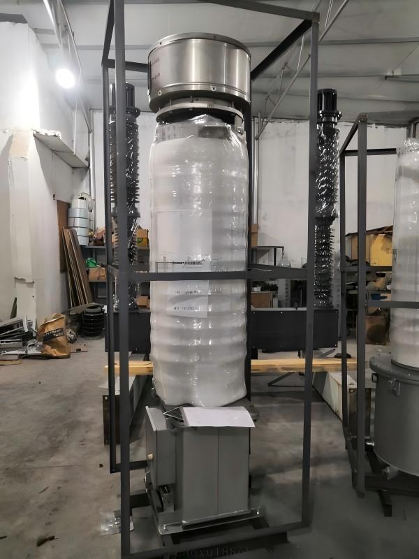
Different station areas use different CT constructions. The best type depends on voltage level, available space, insulation medium, and maintenance strategy.
Wound CT: used where a primary winding is needed for lower current or special ratio requirements
Bar-type CT: common in switchgear and bus applications with a solid primary conductor
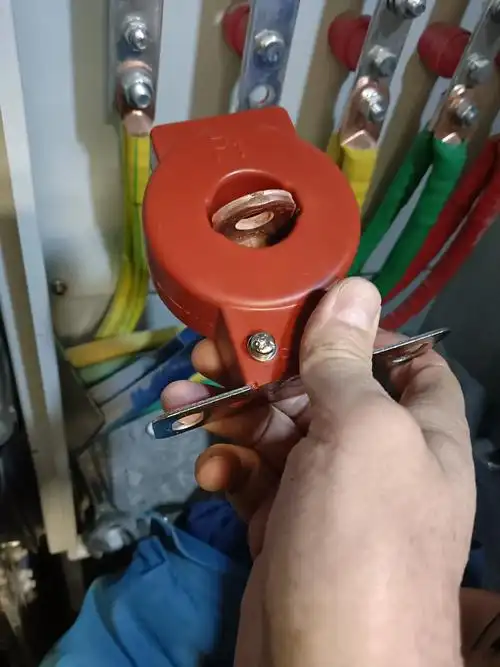
Ring-type CT: widely used on cables, bushings, and compact panels
Bushing CT: integrated into transformer, breaker, or generator transformer bushings
Outdoor oil or SF6-free live tank CT: common in outdoor high voltage yards
GIS-compatible CT: designed for gas-insulated substations with compact footprints and high reliability
In modern substations, utilities increasingly prefer designs with lower maintenance requirements and reduced environmental risk, especially where oil containment or gas handling adds operational burden.
How to Calculate Metering Current Transformer Ratio
Metering current transformer ratio calculation should start with the actual continuous load current, not the fault current. Metering performance matters most in the normal operating range.
Basic CT Ratio Formula
The nominal CT ratio is:
CT ratio = Primary rated current / Secondary rated current
Example: if the primary current is 400A and the secondary is 5A, the CT ratio is 400/5.
In practice, choose the next suitable standard ratio that keeps expected operating current in a useful measurement band while still accommodating overload margin.
Example: Auxiliary Transformer Feeder at 0.66kV
Assume a 0.66kV auxiliary feeder supplies a motor control section with a continuous load of 320A and occasional overload up to 360A. A practical metering ratio could be 400/5 or 400/1.
If the relay room is far away and cable runs are long, 400/1 will usually reduce burden and improve effective accuracy. If the board is a retrofit with legacy 5A meters, 400/5 may be more practical.
Example: Generator Outlet CT at 13.8kV / 14.4kV Class
Consider a 25MVA generator on a 13.8kV system using 14.4kV class equipment. Full-load current is approximately:
I = 25,000kVA / (1.732 × 13.8kV) ≈ 1,046A
A standard ratio such as 1200/1 is often suitable for generator-side metering and protection, depending on overload expectations and relay design. If separate cores are used, the metering core may stay at 1200/1 while a dedicated protection core is selected for the required class and knee point performance.
CT Accuracy Class and Burden for Power Station Applications
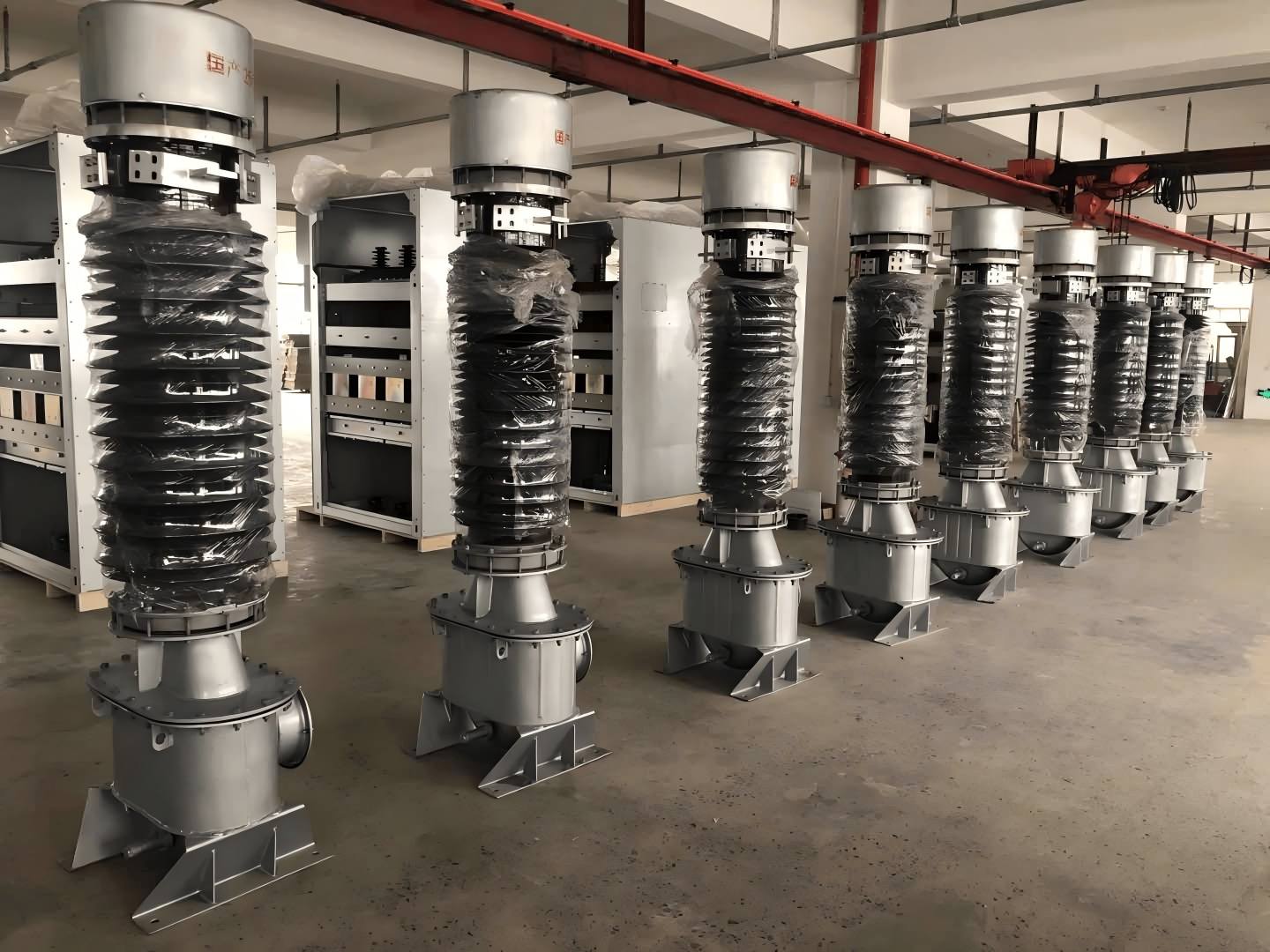
Power station CT accuracy class and burden affect everything from revenue metering to generator differential stability. A technically correct ratio can still fail in service if the burden is excessive or the class is unsuitable.
Typical Metering Accuracy Classes
Common metering classes include 0.2, 0.2S, 0.5, and 0.5S. Revenue and high-precision energy measurement typically use finer classes, while SCADA trending and supervisory monitoring may accept less stringent accuracy.
For billing interfaces, plant export metering, and performance guarantees, the specified class should be coordinated with the meter manufacturer and utility requirements.
Typical Protection Accuracy Classes
Protection applications commonly use classes such as 5P10, 5P20, 10P10, PX, PS, or TP classes, depending on the relay function and applicable standard.
Overcurrent relays may work well with standard protection classes. Differential, REF, and busbar schemes often require special performance classes with defined knee point, winding resistance, and excitation characteristics.
How Cable Length Increases CT Burden
Long secondary wiring adds resistance, and resistance increases VA burden. This can push the CT outside its intended accuracy range.
For example, a remote relay panel 80 to 120 meters away can materially increase burden, especially with 5A secondaries. This is one reason 1A circuits are commonly favored in large power stations.
Protective Current Transformer Sizing for Generators
Protective current transformer sizing for generators is one of the most demanding CT applications in a station. Generator faults can involve high asymmetry, DC offset, and strict relay stability requirements.
Generator Differential Protection CT Considerations
Generator differential protection depends on matching CT behavior across the protected zone. Ratio mismatch, unequal saturation, or poor knee point selection can produce false differential current.
In practice, engineers verify ratio, class, knee point voltage, excitation current, winding resistance, transient performance, and lead burden on both sides of the protection zone. This is especially important on generator-transformer units.
Neutral, Phase, and Auxiliary CT Coordination
Phase CTs and neutral CTs must work together in schemes such as restricted earth fault and stator ground fault protection. Coordination errors can reduce sensitivity or create false operation.
For this reason, generator protection design often uses dedicated CT cores for phase differential, neutral protection, backup overcurrent, and metering rather than sharing one core across all functions.
High Voltage Substation Current Transformer Specifications
High voltage substation current transformer specifications go far beyond ratio and class. In step-up substations and switchyards, insulation, mechanical strength, environment, and core allocation are equally critical.
126kV CT Selection Criteria
For 126kV class switchyards, verify insulation coordination, creepage distance for site pollution level, outdoor weather performance, thermal current rating, and the number of metering and protection cores.
Typical uses include generator step-up transformer HV terminals, line bays, bus couplers, and transfer bus positions in 110kV or 115kV class systems.
252kV CT Selection Criteria
At 252kV, BIL and switching surge withstand become more demanding. Core allocation also becomes more important because line protection, busbar protection, backup relays, metering, and disturbance recording may all require dedicated inputs.
Utilities may also require seismic qualification, anti-ferroresonance design considerations, and strict relay security during high through-fault conditions.
550kV CT Selection Criteria
At 550kV, EHV insulation coordination is a major design driver. Capacitance effects, transport dimensions, foundation loading, and maintenance access must all be considered early.
For EHV yards, long-term reliability often depends on choosing a proven design with strong factory test records, low maintenance demands, and clear spare-parts support.
International Grid Voltage Classes
Equivalent international classes are widely used in export-oriented and utility-scale projects:
72.5kV CT for 69kV grid
245kV CT for 230kV grid
These mappings are standard in procurement documents and should be stated exactly to avoid confusion between nominal system voltage and equipment rated voltage.
Recommended CT Voltage Classes by Power Station Location
Table: Power Station Area vs CT Voltage Class
| POWER STATION AREA | TYPICAL SYSTEM VOLTAGE | RECOMMENDED CT VOLTAGE CLASS | TYPICAL USE CASE |
|---|---|---|---|
| Auxiliary low voltage board | 0.4kV to 0.66kV | 0.66kV CT | Motor feeders, MCC incomers, auxiliary transformers |
| Small MV generator or feeder circuit | 6.6kV to 7.2kV class | 7.2kV CT | Generator feeders, MV switchgear bays |
| MV switchgear and unit auxiliaries | 10kV to 11kV class | 12kV CT | Unit boards, station service feeders |
| Generator outlet international class | 13.8kV grid | 14.4kV CT | Generator terminals, outgoing generator circuits |
| Large generator or collector system | 33kV to 35kV class | 40.5kV CT | Generator-transformer connection, collector circuits |
| Subtransmission switchyard | 69kV grid | 72.5kV CT | Line bays, transformer bays, bus sections |
| HV switchyard | 110kV to 115kV class | 126kV CT | Step-up substation, line terminals |
| EHV substation | 230kV grid | 245kV CT | Generator step-up transformer HV side, line protection |
| EHV switchyard | 220kV to 230kV class | 252kV CT | Bus couplers, breaker-and-a-half bays, transformer terminals |
| UHV/EHV export switchyard | 500kV class | 550kV CT | Main outgoing lines, interconnection substations |
Real-World Data: Typical CT Ratios in Power Stations
Ratio selection varies with generator rating, transformer MVA, feeder demand, and switchyard fault level. The examples below reflect common engineering practice seen in utility and industrial station projects.
Table: Sample Current Transformer Ratios by Application
| APPLICATION | TYPICAL CONTINUOUS CURRENT | SAMPLE CT RATIO | COMMON SECONDARY | NOTES |
|---|---|---|---|---|
| 0.66kV auxiliary feeder | 280A to 350A | 400/5 | 5A | Often used in legacy auxiliary boards |
| 0.66kV auxiliary incomer | 600A to 750A | 800/1 | 1A | Good for longer panel distances |
| 13.8kV or 14.4kV generator outlet | 950A to 1,100A | 1200/1 | 1A | Common for 20MVA to 30MVA generator units |
| Generator step-up transformer bay | 1,500A to 1,850A | 2000/1 | 1A | Often split across metering and multiple protection cores |
| HV bus coupler or large transformer terminal | 2,300A to 2,700A | 3000/1 | 1A | Frequent in EHV switchyard applications |
These are sample values, not universal rules. Final selection should always follow actual plant current calculations, overload policy, and relay burden review.
Real-World Data: Typical Accuracy, Burden, and Core Allocation
Modern power stations usually apply separate cores for metering, main protection, and backup protection. This reflects real project needs rather than overdesign.
Table: Sample CT Core Configuration for Power Stations
| APPLICATION | RATIO | SECONDARY CURRENT | METERING CLASS | PROTECTION CLASS | BURDEN VA | NUMBER OF CORES |
|---|---|---|---|---|---|---|
| 0.66kV auxiliary incomer | 800/1 | 1A | 0.5 | 5P10 | 5VA to 15VA | 2 |
| 13.8kV generator outlet | 1200/1 | 1A | 0.2S | PX / 5P20 | 10VA to 30VA | 3 to 4 |
| Generator neutral CT | 200/1 | 1A | Not usually required | PX / PS | 10VA to 20VA | 1 to 2 |
| 126kV transformer bay | 2000/1 | 1A | 0.2 or 0.5 | 5P20 / PX | 15VA to 30VA | 3 to 5 |
| 252kV line bay | 3000/1 | 1A | 0.2 | 5P20 / TP class | 15VA to 45VA | 4 to 6 |
These ranges are realistic for many station projects, especially where digital relays, disturbance recorders, SCADA, and utility metering all require dedicated interfaces.
Common Mistakes When Choosing Current Transformers for Power Stations
Most CT problems come from specification shortcuts rather than manufacturing defects.
Choosing the wrong ratio and losing accuracy at normal load
Ignoring actual burden from long cable runs and test switches
Using one core for both metering and protection when duties conflict
Failing to verify knee point for differential or REF schemes
Underrating Ith and Idyn for local fault duty
Not aligning CT voltage class with actual equipment insulation class
Ignoring future expansion such as added relays, meters, or bay extensions
Overlooking neutral CT coordination in generator protection
Assuming all 13.8kV systems use the same equipment class instead of checking whether 14.4kV class equipment is required
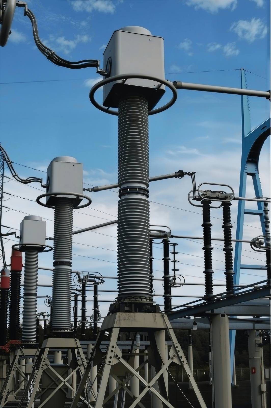
CT Selection Checklist for EPCs, Utilities, and Plant Engineers
Use this short pre-procurement checklist before freezing technical data sheets.
Confirm installation location and exact voltage class
Calculate continuous current and overload margin
Check maximum short-circuit current and required Ith/Idyn
Select 1A or 5A secondary based on burden and station practice
Define metering and protection functions separately
Specify accuracy class and rated burden VA
Calculate total secondary burden including cables
Verify knee point and saturation performance for protection cores
Confirm number of cores for metering, main protection, backup, and SCADA
Review environmental and insulation requirements
Align specification with grid voltage standard such as 14.4kV, 72.5kV, or 245kV where applicable
Require factory routine and type test documentation
FAQ
What is the best current transformer ratio for a power station feeder?
The best ratio is the one that keeps normal operating current inside the CT’s accurate measurement range while still covering overload and fault conditions. In practice, engineers calculate feeder full-load current, add margin, and then choose the nearest standard ratio that avoids both low-load inaccuracy and unnecessary oversizing.
How do I select CT accuracy class and burden for power station metering?
Match the CT class to the metering purpose first, then calculate the full burden of meters, wiring, terminals, and test devices. For billing or export metering, tighter classes such as 0.2 or 0.2S are common, while supervisory monitoring may accept 0.5 or similar classes.
What CT class is used for generator protection?
Generator protection often uses dedicated protection cores such as 5P, PX, PS, or transient performance classes, depending on the relay scheme. Differential and restricted earth fault protection usually require careful review of knee point voltage, excitation current, and stability under high fault current.
Should I use separate metering and protection CT cores?
Yes, separate cores are generally preferred in power stations. Metering precision and protection fault-duty performance often conflict, so dedicated cores improve both accuracy and relay reliability.
How do I choose a CT for a 13.8kV or 14.4kV generator outlet?
Start with the generator full-load current, then confirm the equipment insulation class used by the project. For many 13.8kV systems, 14.4kV class equipment is standard, so the CT must satisfy that class as well as the required ratio, burden, protection core performance, and fault duty.
What are the main high voltage substation current transformer specifications?
The main specifications include voltage class, insulation level, BIL, frequency, ratio, accuracy class, burden, short-time thermal current, dynamic current, number of cores, environmental requirements, and mounting or integration details. For outdoor switchyards, creepage distance and site pollution severity are also critical.
Is 1A or 5A secondary better for power stations?
1A is usually better for long cable runs because it reduces secondary burden and wiring losses. 5A may still be suitable for retrofit projects or legacy installations where existing relays and metering systems are designed around 5A inputs.
How many CT cores are typically needed in a power station bay?
The number depends on metering, main protection, backup protection, busbar schemes, synchronizing, disturbance recording, and SCADA requirements. In many real projects, two to six cores are common for generator and high voltage bays.
Conclusion: Choose CTs Based on Function, Fault Duty, and Voltage Class
The most reliable current transformer selection for power stations comes from matching the CT to its actual job. That means aligning location, voltage class, ratio, secondary current, accuracy class, burden, thermal rating, dynamic rating, and saturation performance.
Whether you are specifying a 0.66kV CT for auxiliary power, a 7.2kV / 12kV / 40.5kV CT for generator outlet duty, or a 126kV / 252kV / 550kV CT for a switchyard, the same rule applies: engineer the CT around the system, not around convenience.
For international projects, remember the common mappings as well: 14.4kV for 13.8kV grid, 72.5kV for 69kV grid, and 245kV for 230kV grid.
Get a Power Station CT Selection Sheet
Do not finalize procurement on assumptions. Use a project-specific CT sizing worksheet or consult a qualified power system specialist to validate ratios, classes, burden, knee point, and switchyard specifications before ordering.
If you are preparing a power station, generator, or substation project, now is the time to build a formal CT selection sheet and review it against your relay philosophy, grid code, and equipment schedule.