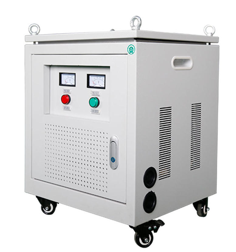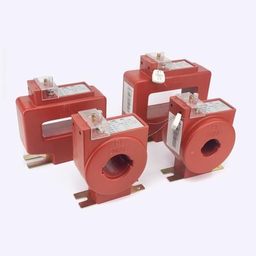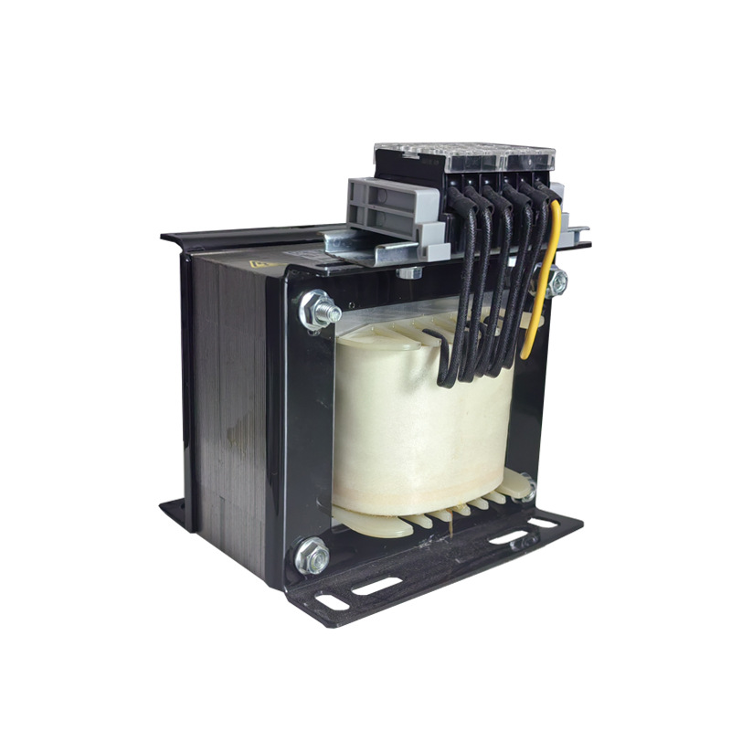
Isolation transformers reduce many voltage spikes by transferring power through magnetic coupling instead of a direct electrical connection. That separation helps limit conductive noise paths, attenuate fast transients, and improve power quality for sensitive equipment.
In real installations, they are especially valuable where common-mode noise, switching transients, and grounding-related disturbances cause resets, data errors, or signal interference. They are not a complete replacement for surge protective devices, but they are a critical layer in a serious protection strategy.
What Causes Voltage Spikes in Real-World Electrical Systems?
Voltage spikes are very short-duration overvoltage events. In practice, engineers may also call them surges or transients, depending on waveform shape, duration, and source.
Common real-world causes include lightning activity, utility switching, capacitor bank operations, transformer energization, and fault clearing on the distribution network. Inside facilities, many spikes come from motors, contactors, welders, compressors, and VFD-driven loads.
Lightning-induced events: Can couple into building wiring even without a direct strike.
Motor switching: Creates abrupt changes in current and magnetic fields.
Utility faults: Reclosing operations and feeder disturbances can generate transients.
VFDs and power electronics: High-frequency switching can inject conducted noise and steep-edge disturbances.
According to IEEE power quality practices, transient disturbances are a major contributor to unexplained control system upset. In industrial plants, nuisance trips often trace back not to sustained overvoltage, but to short, repetitive switching events.
Why Voltage Spikes Damage Sensitive Equipment
Sensitive electronics are built around semiconductors, digital logic, communication interfaces, and low-voltage control power supplies. These components can malfunction long before a spike is large enough to cause obvious physical damage.
PLCs may reset or latch faults. Medical devices can experience imaging errors or unstable operation. Servers may log power anomalies, while audio systems can produce hum, clicks, or elevated noise floors.
Industrial controls: I/O errors, false triggering, communication dropouts.
Medical equipment: Image artifacts, calibration drift, unexplained reboots.
IT systems: PSU stress, data corruption risk, shortened component life.
Broadcast and audio gear: Audible interference and ground-related noise.
The damage mechanism is not always catastrophic. Often, repeated transient exposure slowly degrades insulation, power supply components, MOVs, interface chips, or signal integrity margins.
How Does an Isolation Transformer Reduce Voltage Spikes?
An isolation transformer passes energy through a magnetic field between primary and secondary windings. Because there is no direct metallic connection between the two circuits, many disturbances are reduced before they reach the load.
This is the basis of isolation transformer surge suppression. The transformer does not “erase” all overvoltage, but it can reduce the transfer of fast-rising transients, common-mode noise, and coupled interference.
Galvanic Isolation for Spike Protection
Galvanic isolation for spike protection means the source and load are electrically separated. That separation interrupts direct conductive paths that would otherwise carry some disturbances straight into sensitive equipment.
If a transient rides on the source reference relative to ground, the lack of a direct connection helps prevent identical downstream reproduction. This is especially useful where grounding systems are imperfect or where upstream equipment creates noise relative to earth.
Common Mode Noise Reduction Transformer Effects
A common mode noise reduction transformer helps reduce noise that appears in the same direction on line and neutral relative to ground. This matters in facilities with VFDs, switch-mode power supplies, and mixed analog-digital loads.
Shielding between windings, physical separation, and transformer geometry all help limit capacitive coupling. In shielded designs, electrostatic shields can divert high-frequency common-mode currents to ground before they reach the secondary.
Voltage Transient Attenuation in Transformers
Voltage transient attenuation in transformers occurs because real transformers are not perfect conductors. Leakage inductance, distributed capacitance, winding resistance, and overall impedance influence how high-frequency events are transmitted.
Fast transient edges are often softened as they pass through the transformer. In simple terms, the transformer behaves less like a transparent wire and more like a frequency-dependent barrier.
This effect is strongest for high-frequency transients and weaker for slow, high-energy overvoltage events. That is why isolation transformers help with many switching spikes but are not stand-alone lightning protection devices.
EMI Filtering With Isolation Transformer Design
EMI filtering with isolation transformer design is most effective when the transformer includes a Faraday shield or grounded screen between primary and secondary windings. This improves high-frequency noise rejection and reduces capacitive transfer.
Many engineered power-conditioning systems also pair the transformer with line filters, surge protective devices, or secondary suppression components. That combination improves both conducted EMI control and surge suppression performance.
Do Isolation Transformers Stop All Surges?
No. Isolation transformers reduce many fast spikes and common-mode noise events, but they do not replace a coordinated surge protection system.
Large lightning surges, service entrance events, and high-energy fault-related overvoltages require properly selected surge protective devices, grounding, bonding, and sometimes a layered protection scheme from service entrance to point of use.
Think of an isolation transformer as a power quality and transient attenuation tool. Think of an SPD as a high-energy clamping device. In critical systems, both are usually needed.
Isolation Transformer vs Surge Protector: What Is the Difference?
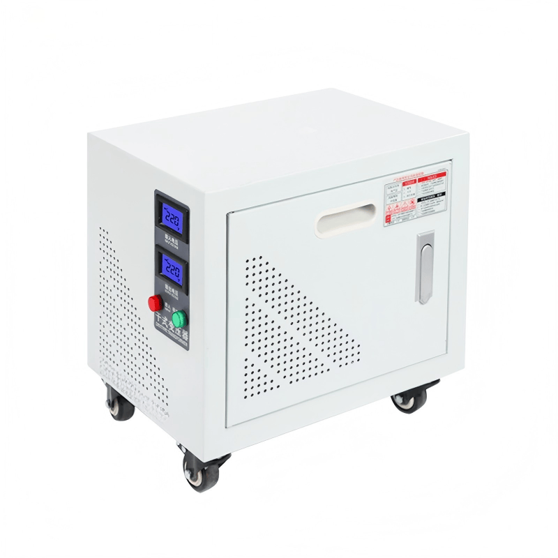
An isolation transformer and a surge protector solve different electrical problems. They can work together, but they do not operate the same way.
| Device | Primary Function | How It Works | Best At | Limitations |
|---|---|---|---|---|
| Isolation Transformer | Electrical isolation and noise reduction | Magnetic coupling between separate windings | Common-mode noise reduction, transient softening, grounding isolation | Does not clamp major surge energy like an SPD |
| Surge Protector (SPD/MOV-based) | Overvoltage clamping | Diverts excess voltage to ground or between conductors | Lightning-related surges, utility transients, high-energy events | Limited help with ongoing noise and ground-related interference |
In practice, the best design often uses a service entrance SPD, local branch protection, and an isolation transformer near critical loads.
Where Isolation Transformers Work Best for Surge Suppression
Isolation transformers deliver the most value where equipment is sensitive, uptime matters, and electrically noisy loads share the same distribution system.
Medical rooms: Imaging, diagnostic, and patient-adjacent equipment.
CNC equipment: Controls exposed to spindle drives, motors, and contactors.
Telecom racks: Network electronics vulnerable to ground noise and transients.
Broadcast studios: Audio/video systems needing low noise and stable reference.
Laboratory instruments: Precision analyzers, measurement platforms, and calibrated test gear.
They are also common in semiconductor tools, automation cells, printing systems, and metrology environments where electrical noise translates directly into quality loss or downtime.
Real-World Examples of Isolation Transformer Surge Suppression
Field results vary by system design, grounding, source impedance, and transient source. Still, many facilities report measurable reductions in nuisance resets, audible interference, and waveform contamination after adding a properly specified shielded isolation transformer.
Example: Industrial PLC Panel Near Motor Loads
A manufacturing line with multiple 30 hp motors and VFDs experienced intermittent PLC communication faults during frequent starts and stops. Power quality review showed repetitive switching transients and common-mode noise on the control power feed.
After installing a shielded isolation transformer dedicated to the PLC panel and correcting grounding layout, the plant reported a sharp drop in nuisance faults. Maintenance logs showed resets falling from several per week to occasional rare events during severe upstream disturbances.
This is a classic case for common mode noise reduction transformer performance. The transformer did not eliminate all disturbances, but it significantly improved control stability.
Example: Hospital Imaging Room Power Quality Upgrade
A hospital imaging room experienced periodic equipment instability during operation of nearby mechanical systems. The engineering team identified conducted noise and building-side transients coupling into the diagnostic equipment branch.
A medical-grade shielded isolation transformer, combined with improved bonding and upstream SPD coordination, improved power stability. Staff reported fewer unexplained interruptions, and service calls related to power quality dropped after the upgrade.
In healthcare facilities, galvanic isolation for spike protection is valued not only for surge reduction, but also for cleaner reference conditions and safer segregation of sensitive loads.
Example: Audio Studio With Ground Noise and Spike Issues
A broadcast studio suffered from audible hum, intermittent clicks, and sensitivity to nearby HVAC switching. The issue was not just overvoltage, but a combination of common-mode interference and ground-related noise.
Installing an isolation transformer with electrostatic shielding on the technical power feed reduced hum and improved overall noise performance. Engineers also observed fewer spike-related glitches in digital audio interfaces.
This is a strong example of EMI filtering with isolation transformer principles in action. The result was cleaner audio and more reliable operation, not merely surge survivability.
How Isolation Transformers Attenuate Different Disturbances
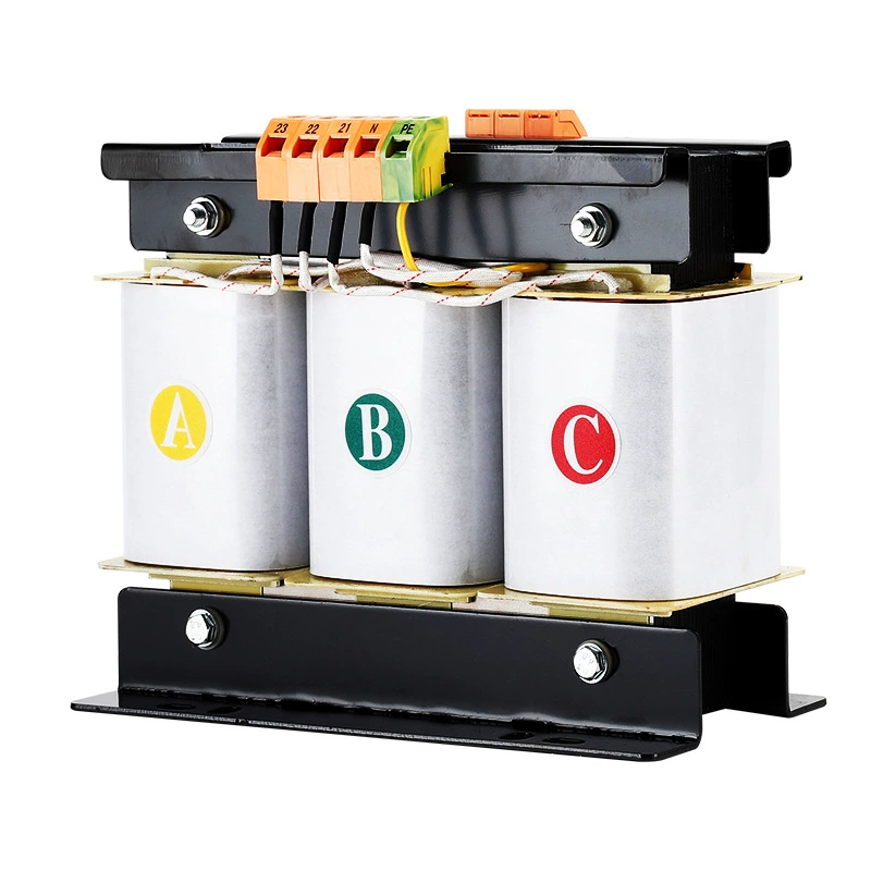
The exact attenuation depends on design, shielding, grounding, wiring layout, and disturbance frequency. The ranges below are realistic field-oriented estimates, not universal guarantees.
| Spike or Disturbance Type | Typical Source | Typical Frequency Content | Transformer Effect | Expected Attenuation Range |
|---|---|---|---|---|
| Fast common-mode switching spike | VFDs, contactors, SMPS equipment | High frequency, often tens of kHz to MHz | Shielding and winding separation reduce capacitive coupling | 10 dB to 40 dB common-mode reduction, design dependent |
| Motor switching transient | Across-the-line motor starts, relay opening | Broadband transient with fast edge | Leakage inductance and impedance soften edge transfer | Moderate attenuation; often noticeable reduction in nuisance faults |
| Utility switching surge | Capacitor banks, feeder switching | Lower frequency than EMI, but still transient in nature | Partial attenuation only | Limited to moderate; SPD still recommended |
| Ground-referenced common-mode noise | Shared grounding, nearby power electronics | kHz to MHz range common in facilities | Galvanic isolation interrupts direct conductive path | Often substantial improvement when shielded and grounded correctly |
| Direct lightning-related surge coupling | Nearby or direct lightning event | Very high energy impulse | Transformer alone is insufficient for full protection | Minimal as sole protection method; use coordinated SPDs |
Isolation Transformer vs Other Power Protection Devices
| Device | Main Benefit | Best For | Weakness | Typical Use Case |
|---|---|---|---|---|
| Isolation Transformer | Galvanic isolation, common-mode noise reduction, transient attenuation | Sensitive electronics in noisy environments | Not a substitute for high-energy surge clamping | Medical, industrial control, audio, lab equipment |
| Surge Protector (SPD) | Clamps overvoltage events | Lightning and utility-related surges | Does not provide isolation or significant noise cleanup | Service entrances, panels, point-of-use protection |
| Line Reactor | Limits current rise and smooths drive interaction | Motor drive systems | Limited isolation and limited broad noise control | VFD input/output conditioning |
| UPS System | Ride-through during outages and voltage events | Critical IT and continuity loads | May still need upstream SPD and isolation depending on design | Servers, telecom, control systems |
| EMI Filter | High-frequency conducted noise reduction | Noise-sensitive circuits | Not designed for major surge energy alone | Instrumentation, electronics, compliance-driven systems |
What Factors Determine Spike Reduction Performance?
Not all isolation transformers perform equally. Real surge and noise reduction depend on several engineering variables.
kVA size: A transformer must be sized for the actual load and inrush profile.
Shielded vs unshielded design: Electrostatic shielding usually improves common-mode rejection.
Grounding quality: Poor grounding can severely limit noise reduction benefits.
Source impedance: Upstream system characteristics affect transient behavior.
Load type: Digital electronics, motors, and mixed loads respond differently.
Installation layout: Cable routing, panel separation, and bonding matter greatly.
One common mistake is focusing only on transformer rating while ignoring layout and grounding. In many field cases, those installation details determine whether performance is excellent or disappointing.
Best Practices for Using Isolation Transformers for Voltage Spike Protection
For reliable results, isolation transformers should be part of a layered power quality strategy. The transformer works best when integrated into good electrical design rather than used as a stand-alone fix.
1. Pair with SPDs: Use service entrance and local surge protection for high-energy events.
2. Use proper bonding: Ensure shield grounding and equipment grounding are correctly implemented.
3. Keep grounding paths short: Long grounding conductors reduce suppression effectiveness.
4. Protect upstream: Coordinate branch circuits, panels, and feeder protection.
5. Check maintenance status: Inspect terminations, overheating, and grounding integrity periodically.
Where VFDs or heavy switching loads exist, physically separating noisy circuits from protected secondary wiring also improves results.
Common Mistakes When Using Isolation Transformers for Surge Control
Isolation transformers are effective, but misapplication is common. Several errors repeatedly show up in field troubleshooting.
Assuming bigger is always better: Oversizing does not automatically improve transient attenuation.
Ignoring grounding: Even a premium transformer underperforms with poor bonding.
Expecting lightning immunity: High-energy surge protection still requires SPDs.
Bad panel layout: Routing noisy and clean conductors together can reintroduce interference.
Using unshielded models in noise-critical applications: This limits common-mode rejection.
Another mistake is failing to evaluate the actual disturbance source. If the problem is differential surge energy from the utility, an SPD may produce a bigger immediate benefit than transformer isolation alone.
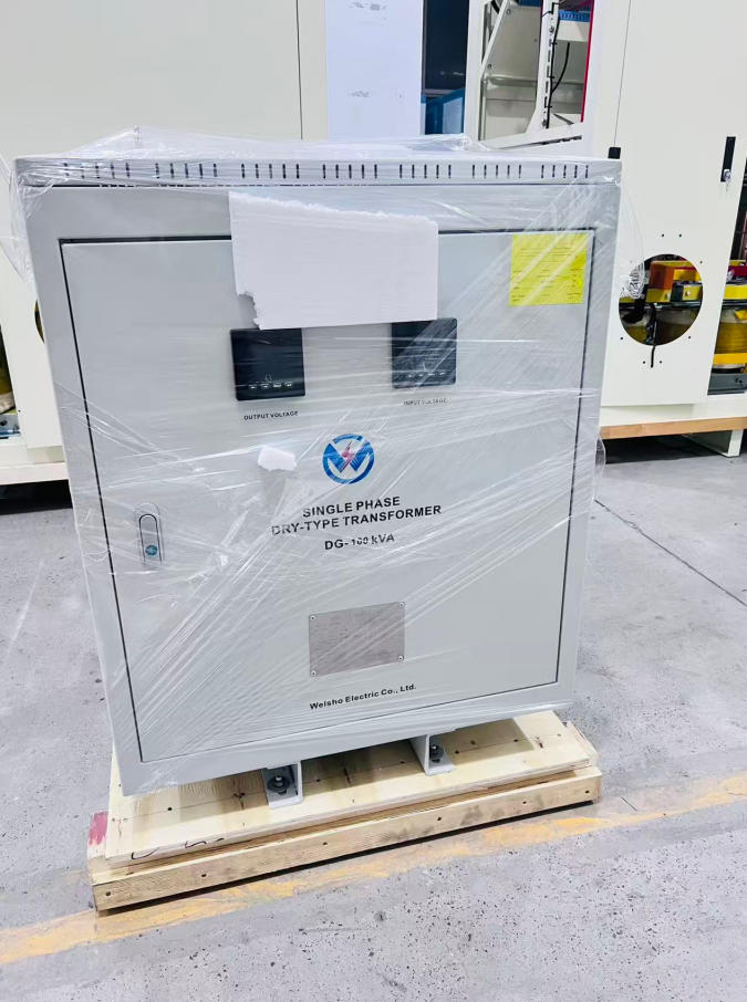
How Do Isolation Transformers Reduce Voltage Spikes?
Isolation transformers reduce voltage spikes by transferring power through magnetic coupling instead of a direct electrical connection. Their galvanic isolation, winding separation, shielding, and inherent impedance help attenuate common-mode noise and soften fast electrical transients before they reach sensitive downstream equipment.
FAQ
Can an isolation transformer protect against lightning surges?
It can reduce some transient coupling, especially fast common-mode disturbances, but it should be combined with a properly rated surge protective device for direct or high-energy lightning events.
Do shielded isolation transformers work better for voltage spike reduction?
Yes. Electrostatic shields usually improve common-mode noise rejection and reduce capacitive coupling between primary and secondary, which often improves transient isolation performance.
Is an isolation transformer better than a surge protector?
No single device is universally better. An isolation transformer provides galvanic isolation and noise reduction, while a surge protector clamps high-energy overvoltage events. In most critical applications, using both together delivers better protection.
How much voltage spike attenuation can an isolation transformer provide?
Realistic performance varies widely by design, shielding, grounding, installation, and transient frequency. For high-frequency common-mode noise, improvement may range from about 10 dB to 40 dB, while attenuation of slower, higher-energy surges is usually much more limited.
Can isolation transformers reduce EMI and common-mode noise too?
Yes. They are often selected specifically for common-mode noise reduction and EMI filtering with isolation transformer-based power conditioning, especially when shielded designs and proper grounding are used.
Where should an isolation transformer be installed?
It should usually be installed close to the sensitive load it is meant to protect, with proper grounding, short bonding paths, and coordinated upstream surge protection to limit incoming disturbances effectively.
Conclusion and Next Step
Isolation transformers are a proven tool for reducing many voltage spikes, cleaning up common-mode noise, and improving downstream power quality. Their value comes from magnetic coupling, galvanic isolation for spike protection, shielding, and the natural voltage transient attenuation in transformers.
They work especially well for medical systems, industrial controls, telecom equipment, audio environments, and precision instruments. But the strongest results come when they are specified correctly and combined with SPDs, proper grounding, and disciplined installation practices.
CTA
Do not wait for the next reset, failure, or service interruption. Evaluate your facility’s power quality risks now and request a professional isolation transformer sizing or surge protection consultation today.
Take the next step: review your load profile, identify transient sources, and choose a protection strategy that combines isolation transformer surge suppression with coordinated surge defense for long-term equipment reliability.