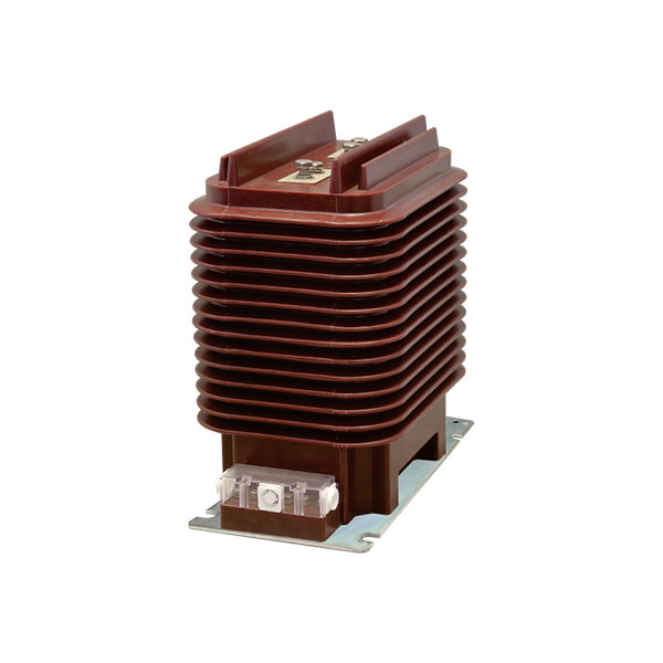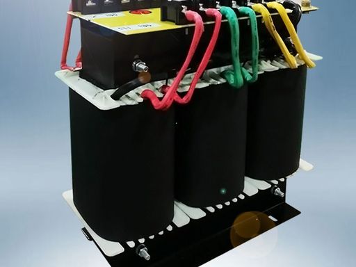
Choosing between an autotransformer and a two-winding transformer affects safety, efficiency, cost, and long-term reliability.
This guide explains the difference between autotransformer and transformer designs in practical engineering terms, using real-world examples, data tables, and selection criteria you can apply immediately.
What Is the Difference Between an Autotransformer and a Transformer?
An autotransformer uses a single continuous winding with one or more taps. Part of that same winding acts as both the primary and the secondary.
A standard two-winding transformer uses separate primary and secondary windings linked only by magnetic flux in the core.
The main difference is simple: an autotransformer has a shared winding, while a conventional transformer has electrically isolated windings.
That single design difference drives almost every performance outcome, including cost, efficiency, isolation, size, and fault behavior.
Why Choosing the Wrong Transformer Type Can Cause Cost, Safety, and Efficiency Problems
Selecting the wrong transformer type can increase project cost without improving performance.
For example, using a two-winding transformer for a small voltage adjustment such as 230 V to 200 V may add unnecessary copper, weight, and purchase cost.
The reverse mistake is more serious. Using an autotransformer where galvanic isolation is required can expose equipment and users to shock and fault-transfer risks.
This matters in medical systems, laboratory benches, control circuits, and sensitive electronics.
Efficiency can also suffer. In close-ratio voltage conversion, a two-winding transformer often wastes more material and has slightly higher losses than an autotransformer.
Across continuous industrial operation, even a 1% to 2% efficiency gap can become meaningful in annual energy cost.
Autotransformer vs Two Winding Transformer at a Glance
When comparing autotransformer vs two winding transformer designs, engineers usually focus on isolation, material use, efficiency, voltage ratio, and safety.
The table below summarizes the most important differences.
Table: Autotransformer vs Two Winding Transformer
| Parameter | Autotransformer | Two-Winding Transformer |
|---|---|---|
| Winding design | Single tapped winding shared by input and output | Separate primary and secondary windings |
| Electrical isolation | No galvanic isolation | Full galvanic isolation |
| Copper use | Lower | Higher |
| Core material | Usually less for close voltage ratios | Usually more |
| Efficiency | Typically higher | Typically slightly lower |
| Size and weight | Smaller and lighter | Larger and heavier |
| Cost | Usually lower | Usually higher |
| Voltage ratio suitability | Best for close ratios | Suitable for wide or close ratios |
| Fault transfer risk | Higher, because circuits are electrically connected | Lower, because windings are isolated |
| Typical uses | Motor starting, grid interconnection, line voltage adjustment | Isolation, control panels, medical/lab loads, sensitive electronics |
How an Autotransformer Works
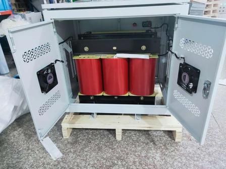
The autotransformer working principle is based on a single winding wrapped around a magnetic core.
A portion of that winding is common to both the input and the output, while a tap selects the required voltage.
Power transfer happens in two ways at once: partly through direct electrical conduction and partly through electromagnetic induction.
This is why autotransformers can achieve high efficiency with less copper than an isolated transformer.
Step-Up and Step-Down Operation
In step-down operation, the supply is applied across the full winding, and the load is connected across a smaller tapped portion.
For example, a 230 V supply may be reduced to 200 V by selecting the appropriate tap.
In step-up operation, the supply is applied across a portion of the winding, and the load is connected across a larger portion.
A common example is raising 200 V to 230 V for equipment compatibility.
How a Two-Winding Transformer Works
A two-winding transformer has separate primary and secondary coils wound on a shared magnetic core.
When alternating current flows in the primary winding, it creates a changing magnetic flux in the core.
That magnetic flux induces a voltage in the secondary winding according to the turns ratio.
Because there is no direct electrical connection between the two windings, the design provides galvanic isolation.
This isolation is the biggest reason engineers still choose standard transformers even when they cost more and weigh more.
Difference Between Autotransformer and Transformer in Core Performance Areas
The real decision is not theoretical. It comes down to how both designs behave in the areas that matter most in the field.
Electrical Isolation
A standard transformer provides galvanic isolation because the primary and secondary are physically separate.
An autotransformer does not provide that protection because part of the winding is shared.
If isolation is required for user protection, noise reduction, grounding strategy, or code compliance, a two-winding transformer is usually the correct choice.
Efficiency
Autotransformers are often more efficient because they use less copper and usually experience lower I²R loss for the same duty.
In close-ratio conversion, efficiencies above 98% are common in practical designs.
Two-winding transformers are also highly efficient, but they often run slightly lower in similar ratings because all power transfers by induction and the material requirement is higher.
Size and Weight
Because the autotransformer shares winding material, it is generally smaller and lighter than an equivalent isolated transformer.
This matters in panel design, skid packages, HVAC equipment, and retrofit installations where space is limited.
Cost
Autotransformers are usually cheaper because they require less copper, less insulation material, and often a smaller core.
For high-kVA equipment and close voltage ratios, the capital cost difference can be substantial.
Voltage Regulation
Autotransformers often show good voltage regulation because of lower impedance and reduced winding resistance.
This can be useful where a stable output under changing load is important.
Two-winding transformers may have somewhat higher impedance, which can mean slightly more voltage drop under load.
However, that same impedance can also help limit fault current in certain systems.
Safety and Fault Risk
The lack of isolation in an autotransformer means input-side surges, faults, or grounding problems can appear on the output side more directly.
That raises risk in human-accessible or sensitive systems.
Two-winding transformers reduce fault transfer between circuits and improve shock protection strategy.
That is why they are widely preferred in control, medical, test, and safety-critical applications.
Autotransformer Advantages and Disadvantages
A balanced evaluation is essential. The best design depends on the application, not just on price.
Advantages of an Autotransformer
Lower cost due to reduced copper and insulation
Smaller size for the same voltage conversion duty
Lighter weight, which simplifies installation
Higher efficiency, especially for close voltage ratios
Better material utilization, often allowing higher VA output for the same amount of copper and core
Good voltage regulation in many practical systems
Disadvantages of an Autotransformer
No electrical isolation between source and load
Higher fault current risk because of lower impedance and direct connection
Greater shock hazard potential in some fault scenarios
Limited suitability for medical, laboratory, residential isolation, and sensitive electronics applications
Not a substitute for an isolation transformer where code or safety requires separation
Real-World Data and Examples: When an Autotransformer Outperforms a Standard Transformer
The strongest case for an autotransformer appears when the voltage ratio is close, and isolation is not required.
In those cases, the savings in material, energy, and footprint can be real and measurable.
Utilities, motor-control designers, HVAC engineers, and equipment importers use autotransformers for exactly these reasons.
Table: Example Comparison for 10 kVA, 230 V to 200 V Conversion
The following values are indicative industry estimates for a close-ratio conversion application.
Exact values vary by manufacturer, insulation class, impedance target, enclosure, and cooling method.
| Metric | Autotransformer (10 kVA, 230 V to 200 V) | Two-Winding Transformer (10 kVA, 230 V to 200 V) |
|---|---|---|
| Estimated efficiency at full load | 98.5% to 99.0% | 96.5% to 98.0% |
| Relative copper use | About 25% to 40% less | Baseline |
| Typical weight | About 20 kg to 30 kg | About 30 kg to 45 kg |
| Purchase cost | Often 15% to 35% lower | Higher |
| Isolation | No | Yes |
| Best fit | Voltage matching where isolation is unnecessary | Safety-sensitive and isolated supply applications |
In a continuously loaded 10 kVA system operating 4,000 hours per year, a 1.5% efficiency advantage can avoid roughly 600 kWh of annual losses.
At an electricity rate of $0.12 per kWh, that equals about $72 per year, excluding cooling or demand impacts.
Industrial Motor Starting Example
Autotransformer starters have long been used to reduce inrush current during motor starting.
This is common in large pumps, compressors, conveyors, and HVAC chillers.
A full-voltage induction motor may draw 6 to 8 times full-load current at startup.
With an autotransformer starter using an 80% tap, line current can be reduced significantly while still delivering useful starting torque.
Because motor torque is approximately proportional to the square of applied voltage, 80% voltage gives about 64% starting torque.
This makes autotransformer starting a practical compromise between full-voltage starting and more advanced electronic drives.
Voltage Conversion Example for Imported Equipment
Autotransformers are widely used for regional voltage adaptation, such as 120 V to 230 V or 230 V to 120 V, when the equipment does not require isolation.
This is common with industrial tools, commercial appliances, and some resistive or motor-based loads.
However, engineers must verify grounding, leakage, insulation system compatibility, and manufacturer approval before using this approach.
For consumer-accessible or sensitive electronics, an isolation transformer may still be the safer choice.
Power Distribution Example
In transmission networks, autotransformers are frequently used where voltage ratios are relatively close.
A well-known example is 400 kV to 220 kV or similar high-voltage interconnection duty.
Utilities favor autotransformers in these roles because they reduce size, losses, and cost at very high power ratings.
In grid applications rated in hundreds of MVA, even small efficiency improvements translate into major lifecycle savings.
Large power-system manufacturers and utility planning standards commonly reserve two-winding transformers for cases where isolation, different grounding arrangements, or larger transformation ratios are required.
Best Applications and Uses for Each Transformer Type
The best choice depends on safety requirements, voltage ratio, and the type of load.
The table below maps common autotransformer applications and uses against standard transformer use cases.
Table: Autotransformer Applications and Uses vs Standard Transformer Applications
| Application | Autotransformer | Two-Winding Transformer |
|---|---|---|
| Motor starting | Excellent fit | Less common |
| Grid interconnection with close voltage ratios | Excellent fit | Used when isolation or grounding separation is needed |
| 120 V/230 V equipment adaptation | Good if isolation is not required | Better when user safety or noise isolation matters |
| Laboratory benches | Usually not preferred | Preferred |
| Medical equipment supply | Generally unsuitable | Preferred |
| Residential isolation | Not suitable | Preferred |
| Control circuits | Limited use | Common and preferred |
| Sensitive electronics | Usually not recommended | Preferred |
| Budget-sensitive industrial voltage trimming | Excellent fit | Often over-specified |
| Large close-ratio high-voltage transformation | Very common | Used selectively |
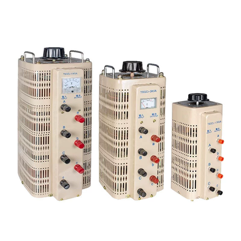
Which One Should You Choose?
The choice becomes easier when you use a short engineering checklist.
Start with isolation, then evaluate voltage ratio, installation environment, budget, and efficiency goals.
Choose an Autotransformer If
You do not need galvanic isolation
The input and output voltages are relatively close
You want to reduce capital cost
You need a smaller, lighter solution
You want high efficiency for voltage matching or motor starting
The application is industrial, and the protection scheme has been engineered properly
Choose a Two-Winding Transformer If
You must have electrical isolation
The system is safety-critical
The load includes sensitive electronics
The application involves medical, laboratory, or user-accessible equipment
You need to separate grounding systems or reduce fault transfer
The voltage ratio is wide enough that autotransformer benefits are less compelling
FAQ
What is the main difference between an autotransformer and a transformer?
The main difference is that an autotransformer uses one shared winding with taps, while a standard transformer uses separate primary and secondary windings. That means the standard transformer provides electrical isolation, but the autotransformer does not.
Is an autotransformer more efficient than a two-winding transformer?
Usually yes, especially when the voltage difference is small. Because part of the power is transferred through a shared winding, autotransformers often use less copper and have lower losses.
Why is an autotransformer cheaper than a standard transformer?
An autotransformer typically needs less copper, less insulation, and often a smaller magnetic core. Those material and manufacturing savings usually make it less expensive than a comparable two-winding transformer.
What are the disadvantages of an autotransformer?
The main disadvantages are no galvanic isolation, higher fault-transfer risk, and limited suitability for sensitive or hazardous applications. It is not the right choice where safety separation is required.
Where are autotransformers commonly used?
Common uses include motor starting, industrial voltage adjustment, imported equipment voltage matching, and high-voltage power transmission interconnection where voltage ratios are close. They are especially popular where efficiency and lower cost matter more than isolation.
Can an autotransformer replace an isolation transformer?
No, not where galvanic isolation is required. An autotransformer cannot provide the same protective separation between source and load as a two-winding isolation transformer.
Which is better for home appliances: autotransformer or transformer?
It depends on the appliance and the safety requirement. For simple voltage conversion of approved equipment, an autotransformer may work, but for sensitive, grounded, or user-accessible appliances, a standard isolated transformer is often the safer option.
Final Verdict: Autotransformer vs Transformer
If you need lower cost, lower weight, and high efficiency for a close voltage ratio and isolation is not required, an autotransformer is often the best solution.
If you need safety, galvanic isolation, fault separation, or protection for sensitive loads, a two-winding transformer is the better choice.
Need Help Choosing the Right Transformer for Your Application?
Do not guess when safety, performance, and lifecycle cost are on the line.
Compare your voltage, kVA, isolation requirement, load type, and installation environment with an expert before you buy.
Request expert guidance, compare specifications, or get a quote now for the right transformer solution based on your exact application.
Share your input voltage, output voltage, kVA rating, frequency, and safety needs today to get a fast recommendation.