I. Introduction: The Core Mechanism of Pad-Mounted Transformers
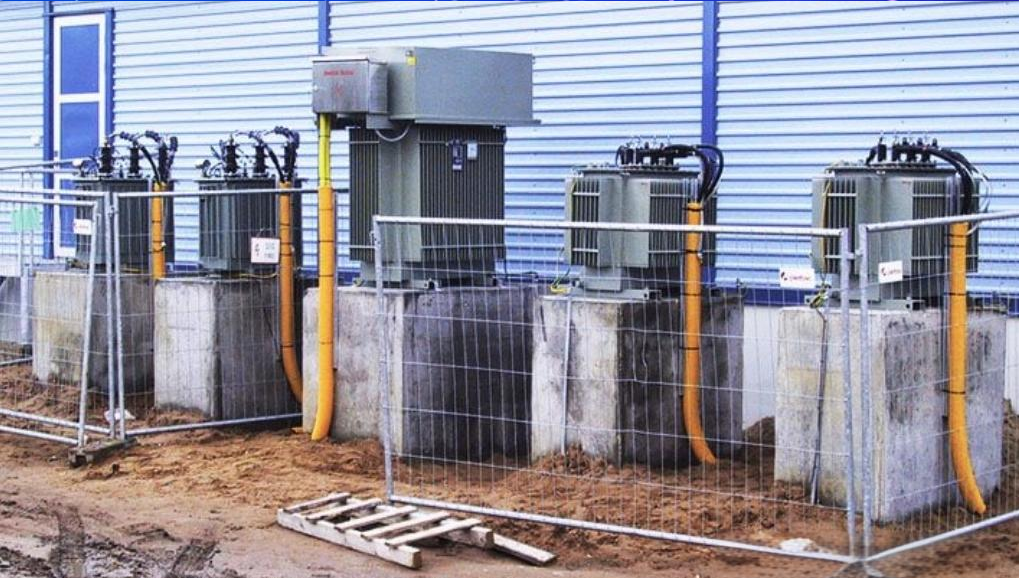
The pad-mounted transformer is an indispensable component of modern underground power distribution networks. It utilizes the principle of electromagnetic induction to safely convert (step down) the ultra-high voltage input from subterranean utility lines into the low voltage (e.g., 120/240 V) suitable for residential and commercial use, all within a robust, locked metal enclosure.
These familiar green or gray boxes, mounted securely on a concrete foundation, act as critical hubs in the electrical transmission chain. They serve as the essential "translators" between the high-voltage transmission grid and the low-voltage consumer endpoint.
They ensure that electrical power reaches every user in a safe, usable, and highly efficient format, often unnoticed but always vital.
Unlike the traditional pole-mounted transformers suspended overhead, the pad-mounted design is a ground-level, fully enclosed structure. This engineering choice significantly enhances urban aesthetics by keeping power lines out of sight. More importantly, its inherent safety isolation features make it the primary choice for high-security power delivery solutions in public spaces.
This deep dive will go beyond basic knowledge, adopting the perspective of an electrical engineer to explore the core electromagnetic theory, the crucial internal components, the structural safety engineering, and the efficiency and loss considerations that govern its operation. We will dissect the engineering principles behind the unit, revealing precisely how it achieves the efficient and safe conversion of complex high-voltage power.
The reliable delivery of electricity is fundamentally tied to the effective step-down process that these transformers manage. Their success in seamlessly integrating into residential and commercial areas is a testament to the rigorous standards of modern utility infrastructure design.
Key Takeaways
The core operating principle of the pad-mounted transformer is Faraday's Law of Electromagnetic Induction, where the precise turns ratio (Primary Turns divided by Secondary Turns) dictates the voltage step-down proportion.
Transformers are categorized into two main types: Single-Phase (primarily serving residential areas, providing 120/240 V) and Three-Phase (serving commercial and industrial loads, demanding higher power capacity), fulfilling distinct distribution needs.
Safety is paramount in its design, featuring a Dead-Front approach that fully insulates and shields all high-voltage connections, combined with a locked steel enclosure and Pressure Relief Valves (PRVs) to guarantee maximum public safety in community installations.
Engineers must meticulously optimize the design to minimize both Core Loss (no-load losses) and Winding Loss (load-dependent losses), which directly improves operational efficiency and reduces utility costs and environmental impact.
The transformer's operation is not static; it is equipped with a Tap Changer, which allows certified technicians to finely tune the output voltage, providing necessary adjustments to accommodate the dynamic fluctuations of the power grid and varying customer loads.
II. The Electrical Engineering Fundamentals of Core Operation
1. The Mathematical Foundation of Electromagnetic Induction
The operation of any transformer relies on a simple yet profoundly powerful physical phenomenon. This foundational principle is Faraday's Law of Electromagnetic Induction.
This law states that when the electric current in one coil changes, the magnetic field it generates changes accordingly. This shifting magnetic field will, in turn, "induce" a voltage and current in a nearby, coupled coil.
Within the pad-mounted transformer, this essential energy conversion occurs inside a highly permeable, laminated iron core. The primary winding receives the high-voltage electricity, and the secondary winding delivers the stepped-down, low-voltage electricity. Energy transmission is achieved contactlessly via the shared magnetic field medium.
The transformer equation, which defines the voltage ratio based on the turns ratio, is the theoretical basis for the step-down mechanism. The Primary Voltage (Vp) divided by the Secondary Voltage (Vs) is strictly equal to the Primary Winding Turns (Np) divided by the Secondary Winding Turns (Ns). By precisely designing Np to be significantly greater than Ns, the transformer can achieve the required substantial voltage reduction, often from thousands of Volts down to 120/240 V.
This mathematical relationship is fundamental to power engineering and dictates the physical construction of the internal windings. Achieving this exact ratio is a crucial step in ensuring the final output voltage meets strict utility standards for safe consumer use.
2. Voltage Conversion and Dynamic Load Management
The transformer's core function is a continuous and dynamic process of electrical energy conversion, managed under constantly changing field conditions. High-voltage current (such as 13.8 kV or 33 kV) is routed from the underground distribution network and enters the primary coil via specialized high-voltage bushings.
This extremely high voltage level is engineered for efficient long-distance transmission but is far too dangerous for direct connection to consumer appliances.
The high-voltage current generates a powerful, alternating magnetic field within the primary coil. The iron core’s essential role is to efficiently constrain and guide this magnetic field to the secondary coil, preventing any unnecessary energy dissipation to the surrounding environment.
Through the controlled turns ratio, the voltage is precisely reduced to a safe and usable level (typically 120/240 V or 208Y/120 V). This usable power is then delivered to the end-user buildings via the secondary cables.
A transformer must be capable of dynamically responding to real-time changes in the downstream customer's current requirements, which are commonly known as load fluctuations. It is not designed for a single constant state of operation.
Engineers must ensure that under the extremes of both maximum and minimum load scenarios, the transformer can consistently maintain a stable output voltage. This prevents damaging voltage spikes or performance-impairing voltage sags.
This inherent ability to adjust to variable demand is what makes the transformer a reliable interface between the robust power grid and the volatile consumption habits of modern users. The entire system must exhibit high resilience to prevent cascading failures during peak usage times.

III. Structural and Electrical Design: From Single-Phase to Three-Phase Applications
The highly customized design of a pad-mounted transformer must always be tailored to meet the specific power demands and regulations of its service area. This customization is primarily reflected in the selection of its phase configuration and winding connection methods.
These choices directly influence the unit's capacity and application.
1. Transformer Types and Detailed Applications
Based on the number of current phases they handle, transformers are rigorously classified into two major categories: Single-Phase and Three-Phase. These two types have significantly distinct structural characteristics and are deployed in entirely different application environments.
Single-Phase Transformers:
Application Scenario: These are predominantly used in residential areas, small commercial settings, or for street lighting. They service low to moderate power loads efficiently.
Specifications: They feature a lower overall load capacity (commonly ranging from 10 kVA to 167 kVA), a generally more compact and simplified design, and typically utilize only two high-voltage bushings for input connection.
Output Voltage: The standard output configuration is usually a three-wire system, precisely providing the 120/240 V power required by the vast majority of standard household appliances.
This design minimizes complexity for lower power demand areas, offering a cost-effective and reliable solution for scattered residential distribution. The inherent simplicity also contributes to faster maintenance and troubleshooting times.
Three-Phase Transformers:
Application Scenario: Employed in large commercial districts, critical facilities like hospitals and data centers, factories, and high-density residential complexes. These locations necessitate stable, high-power delivery to run large mechanical equipment or complex multi-system HVAC units.
Specifications: These units boast a significantly higher load capacity (commonly ranging from 45 kVA up to 5000 kVA), and their external connections necessitate three to six high-voltage bushings for multiple-line input.
Connection Method: Their internal winding configurations, such as the widely used Delta-Wye combination, are vital for maintaining distribution system stability under heavy load. They offer a variety of specific three-phase power standards like 208Y/120 V or 480Y/277 V.
The complex nature of three-phase power allows for smoother, more consistent delivery of torque and power to large motors, which is essential for industrial operations. Proper phase balancing is a continuous engineering concern for these high-capacity installations.

2. Ensuring High-Voltage Connection Safety
The safety engineering of the pad-mounted transformer is its fundamental core value and the main reason for its widespread use in proximity to the public. This high level of protection is most clearly demonstrated in the physical management and isolation of its high-voltage connection points.
The Dead-Front Design is the most significant safety feature and the key allowing these units to be installed in publicly accessible, unfenced areas. This design mandates that all high-voltage connection components—specifically the bushings, connectors, and cable terminals—are entirely covered and grounded by thick insulating sheaths and effective shielding layers.
These materials are typically durable rubber or specialized polymer materials. As a result, when viewing the unit from the exterior, the high-voltage side is completely inaccessible and non-energized to touch, hence the term "Dead."
High-voltage cables are securely connected to the Bushings using specialized Elbow Connectors. This particular connection method is engineered to be both fully waterproof and highly isolated.
This allows specialized utility technicians to perform safe, necessary live-line operation and isolation procedures using dedicated tools like a "Hot Stick."
Tip: The primary advantage of the Dead-Front design is its "touch-safe" nature, which fundamentally alters public interaction with high voltage. Even when the transformer is operating and fully energized, the public is physically prevented from making direct contact with any high-voltage conductor, dramatically minimizing the risk of severe electric shock and dangerous arc flash incidents. This is a critical factor in urban planning and public safety codes across many jurisdictions.
To provide a more intuitive and operational understanding of the pad-mounted transformer’s internal structure and the crucial "dead-front" safety design, a video demonstrating its components and maintenance operation is strategically recommended at this point in the reading. The visual context will greatly enhance the technical descriptions provided previously.
The following video offers a detailed look at the internal connections of a pad-mounted transformer, how the dead-front bushings function, and specifically how certified utility workers use elbow connectors for safe, routine operations:
IV. Operational Efficiency and Loss Analysis
As a critical and costly piece of professional electrical equipment, the design goal for a pad-mounted transformer extends far beyond simply achieving the step-down function. The paramount objective is achieving the highest possible efficiency and the lowest possible loss over its entire operational lifespan, which can span several decades.
This relentless pursuit of efficiency directly impacts the utility company's massive operating expenditures and contributes significantly to the overall sustainability and environmental footprint of energy consumption.
1. Components of Loss and Engineering Optimization
A transformer generates two distinct primary types of power loss during its operation, and the accurate calculation of these losses directly determines the required cooling capacity of the unit. These losses must be managed carefully to ensure longevity.
Core Loss (No-Load Loss):
Cause: This intrinsic power loss is generated within the iron core itself due to the physical phenomena of magnetic hysteresis and circulating eddy currents.
Characteristics: This specific loss is almost entirely independent of the electrical load the transformer is currently serving. As long as the transformer remains connected to the energized grid, this loss continuously occurs, regardless of whether it is actively supplying power to downstream customers.
Engineering Optimization: Engineers must strategically utilize high-quality grain-oriented silicon steel laminations in the core construction to minimize this form of continuous, unavoidable energy waste. The use of thinner laminations and advanced steel alloys reduces the core's magnetic resistance.
Winding Loss (Load Loss):
Cause: This is heat loss, or power dissipation, generated by the current flowing through the inherent electrical resistance of the windings, which are made of either copper or aluminum wires. This loss is directly proportional to the current squared multiplied by the resistance, and is purely described as $I \times I \times R$ loss.
Characteristics: This specific type of loss is proportional to the square of the load magnitude. Consequently, the heavier the current load carried by the transformer, the dramatically greater the winding loss becomes.
Engineering Optimization: By strategically increasing the cross-sectional area of the winding conductors (meaning the use of physically thicker wires) or by utilizing materials with superior electrical conductivity (like high-purity copper), the inherent internal resistance can be effectively lowered. This proactive design measure ensures the minimization of the $I \times I \times R$ losses during heavy load conditions.
2. Cooling and Insulation Systems
The insulating oil (dielectric fluid) within a pad-mounted transformer performs a crucial dual and interconnected function. The primary role of the transformer oil is to efficiently dissipate the heat generated by both the core loss and winding loss.
This keeps the sensitive coils and insulating materials within their optimal design temperature range for continuous, long-term operation.
The insulating oil must simultaneously possess an extremely high dielectric strength to reliably prevent electrical breakdown (internal short circuits) between the high-voltage windings themselves or between the windings and the grounded tank casing. This insulating capability is non-negotiable for system integrity.
Increasingly, modern transformers are utilizing more sustainable and environmentally friendly dielectric fluids, such as natural ester or vegetable-based oils (often branded as FR3 Fluid). These fluids naturally elevate the flash point of the fluid.
This innovation significantly reduces environmental pollution risk, should a leak occur, and substantially enhances the unit’s internal fire safety against catastrophic failure.
Note: A fundamental and unavoidable trade-off exists in transformer design between achieving maximal efficiency and managing the initial capital cost. Low-loss (high-efficiency) transformers inherently require more expensive, higher-grade materials, such as thicker copper wire and premium grain-oriented silicon steel. However, despite the higher upfront investment, these higher-efficiency units save utility companies immense amounts of operating electricity costs over their typical decades-long operational lifecycles, making the high-efficiency approach the most viable and responsible long-term economic choice.

V. Safety and Control: System Protection Mechanisms
The safety and control architecture of the pad-mounted transformer is the central, non-negotiable element that allows it to be seamlessly and safely integrated into congested community environments. This vital protection mechanism is multi-layered.
It encompasses a holistic approach to electrical, mechanical, and public safety considerations.
1. The Fuse System: Core Protection for the Grid
The transformer typically employs a sophisticated and internally coordinated system of fuses, but it is important to note that the primary goal of this system is not to protect the transformer unit from damage itself. Rather, its critical function is to protect the main upstream power grid from the potentially devastating effects of a faulted transformer.
Bay-O-Net Fuses: This specific type of fuse is field-replaceable and typically immersed directly in the insulating oil. They are designed to efficiently clear secondary short circuits or minor internal overloads. Their designed serviceability allows maintenance crews to quickly isolate the fault and restore power following a minor incident.
Current-Limiting Fuses (CLF): These specialized components are robust backup fuses installed in series with the primary winding, and they are rigorously designed to operate only in the event of severe internal faults, such as a winding-to-winding short circuit that could be catastrophic. Their immediate function is to rapidly and forcefully interrupt the circuit before it reaches its maximum possible peak, effectively isolating the failure point and safeguarding the extensive upstream distribution system.
2. Professional Control: Tap Changers and Voltage Regulation
The transformer is not simply a passive component receiving an input voltage; it possesses a carefully engineered capability for active output regulation, and this crucial function is primarily achieved through the utilization of a Tap Changer.
Tap Changer: This is a specialized, multi-position switching mechanism physically mounted onto the windings. It allows a certified technician to precisely alter the number of effective turns in the winding.
Purpose: The device is designed to effectively address long-term systemic fluctuations in the input voltage or seasonal disparities in system load demand. For instance, if the utility grid voltage is consistently measured as running high, a technician can adjust the tap changer to slightly reduce the effective turns on the primary coil, thereby lowering the output voltage and ensuring precise voltage stability at the critical customer endpoint.
3. Physical and Mechanical Safety Guarantees
The Pressure Relief Valve (PRV) serves as the ultimate, indispensable mechanical safety device against catastrophic internal failure. When an internal short circuit or other failure causes a rapid buildup of gas and heat, leading to a dangerous and rapid surge in internal pressure, the PRV is engineered to automatically vent the excess pressure.
This crucial, automated action prevents a catastrophic explosion or rupture of the tank casing, protecting nearby personnel and property.
The robust steel enclosure and locking mechanism ensure unmatched anti-tamper performance and maximum physical security. The heavy-duty 11-gauge steel cabinet, reinforced by careful welding and internal bracing, coupled with specialized safety bolts and highly visible padlock provisions on the outer shell, guarantees that only authorized utility personnel can physically access the high-voltage and low-voltage compartments.
| Component | Category | Functional Description | Protected Target |
| Fuse System (Bay-O-Net / CLF) | Electrical Protection | Dual protection mechanism: Bay-O-net clears low-level faults, while CLF isolates high-energy internal faults, protecting the main power grid. | The Transformer itself, The Power Grid |
| Tap Changer | Voltage Regulation | Allows engineers to fine-tune the winding turns ratio (when de-energized) to maintain voltage stability at the end-user load. | End-user Load, Customer Equipment |
| Pressure Relief Valve (PRV) | Mechanical Safety | Automatically releases pressure during internal faults causing high pressure, preventing casing rupture or explosion. | Transformer Enclosure, Public Safety |
| Locked Steel Enclosure | Physical Isolation | Provides a robust metal structure and locking mechanism to prevent unauthorized public access to high-voltage components. | Public Safety |

VI. Conclusion
The pad-mounted transformer represents a complex and highly specialized system that perfectly integrates foundational electromagnetic principles, cutting-edge precision materials engineering, highly efficient thermal dissipation technology, and multiple overlapping layers of robust public safety protection. The unit's design objective is substantially more complex than just achieving the simple high-to-low voltage conversion.
It is specifically engineered to deliver a stable, reliable power supply in densely populated community settings while consistently adhering to the highest possible standards of safety and energy efficiency.
Every single detailed design element of the pad-mounted transformer, from the meticulous calculation of its turns ratio to the strategic use of silicon steel laminations to rigorously minimize core loss, and the fundamental physical isolation provided by the dead-front bushings, unequivocally reflects the electrical engineer's ultimate commitment to maximizing both operational efficiency and public safety. This critically important device is the indispensable cornerstone of the entire modern urban power distribution network.
A comprehensive understanding of the pad-mounted transformer's operational principles and engineering considerations will not only effectively help to dispel common public misconceptions or potential alarm regarding these ubiquitous "green boxes." More importantly, it will also better equip both the general public and professional personnel to properly maintain and manage this vital piece of critical infrastructure, collectively ensuring the continuous, safe, and reliable operation of the city's essential electrical grid for years to come.

VII. Credible and Helpful FAQ
Q1: Is the insulating oil inside the transformer toxic, and what are its primary roles?
The primary and critical functions of transformer oil are cooling and insulation. The fluid is essential to the transformer's long-term health.
The oil used in modern transformers is typically a highly refined mineral oil or an increasingly common, more environmentally friendly, vegetable-based fluid such as FR3 Fluid. These modern oils possess relatively low toxicity, especially the natural plant-based oils.
These oils also offer a significantly higher flash point, thereby enhancing safety and dramatically reducing environmental risk in case of equipment failure. However, any oil leakage must always be reported immediately as a potential environmental incident to the local utility.
This is because very old transformers might still contain Polychlorinated Biphenyls (PCBs), a highly toxic chemical compound that has long been strictly banned from use.
Q2: Why are some transformers square-shaped while others are cylindrical? Is there a difference in their operating principle?
The difference in the transformer's external shape, whether it is an angular square or a rounded cylindrical form, is typically dictated by the internal winding structure and the specific manufacturer's design preference. There is no fundamental difference in the core operating principle between the two external forms, as both still rely on the same physical laws of electromagnetism.
Cylindrical designs are often strategically chosen to optimize the utilization of internal space and potentially maximize heat dissipation efficiency due to the greater surface-area-to-volume ratio. Rectangular or square designs, conversely, may prove easier and more cost-effective to manufacture, transport, and install upon standard concrete pads.
Ultimately, both shapes must rigorously rely entirely on Faraday's law of electromagnetic induction to achieve the necessary and accurate voltage step-down function.
Q3: If a transformer malfunctions, can the fuses completely protect the power grid?
The fuse system is correctly viewed as the first and most immediate line of defense for the entire power grid. However, it is important to clarify that its main role is to isolate the faulted transformer, rather than to repair or protect the transformer unit itself from the damage that caused the fault.
For example, the Current-Limiting Fuse (CLF) is primarily tasked with rapidly melting and instantly isolating the single faulty unit from the rest of the healthy network when a severe internal short circuit occurs. This action strictly prevents the fault current from propagating and causing a much larger system failure.
Thus, the crucial protection is strictly aimed at the "grid" against the "faulty transformer," rather than ensuring the transformer itself is never damaged by the event.
Q4: What is the "Tap Changer," and can it adjust the voltage while the transformer is running?
The Tap Changer is a specialized mechanical device specifically designed for the fine-tuning of the transformer's output voltage. It achieves this highly necessary regulation by physically changing the number of effective turns in either the primary or secondary windings.
However, pad-mounted transformers, unlike large power station units, typically use a No-Load Tap Changer (NLTC). This crucial distinction means that the utility technician must fully de-energize and safely isolate the transformer from the power source before they can safely operate and adjust the tap settings.
Therefore, this type of unit is unable to perform dynamic voltage regulation while it is energized and actively serving the customer load.
Q5: Why is the transformer's iron core constructed using "laminations" instead of a single piece of solid iron?
The iron core is strategically constructed using a laminated structure, which is essentially a stack of very thin sheets of silicon steel. This construction is used specifically to rigorously minimize Eddy Current Loss throughout its operation.
If a single, thick piece of solid iron core were used, the powerful, changing magnetic field would continuously induce large, circulating eddy currents within it. This would inevitably lead to a significant amount of electrical energy being pointlessly wasted as heat and severely reduce the overall operating efficiency.
By utilizing thin, electrically insulated steel sheets (the laminations), the path for the induced eddy current is intentionally broken, or its resistance is drastically increased. This strategically confines the currents within each thin sheet and significantly reduces the overall energy loss, which directly lowers the intrinsic core loss.