Why Generator Neutral Cubicle CT Selection Matters
The current transformer inside a generator neutral cubicle is a small device with a very large job. If it is selected correctly, it helps protection relays detect earth faults early, avoid false trips, and prevent thermal and insulation damage inside the generator stator winding.
If it is selected incorrectly, the protection system may either become too sensitive or not sensitive enough. In real plants, both failures are expensive: nuisance tripping causes lost production, while missed neutral faults can escalate into winding failure, core damage, or extended outages.
Generator neutral protection is not a generic feeder protection problem. The fault currents are often intentionally limited by a neutral grounding resistor, reactor, or high-resistance grounding scheme, so the CT must be able to measure relatively low currents with dependable accuracy.
This is exactly why generator neutral grounding cubicle current transformer sizing deserves a disciplined engineering process instead of rule-of-thumb selection.
The Core Problem: Why Neutral CTs Are Often Selected Incorrectly
Neutral CTs are often chosen using habits borrowed from line-side protection. That is one of the main reasons errors happen.
On the generator terminals, engineers may be used to high current ratings, large fault levels, and conventional protection classes. In the neutral cubicle, the operating conditions are different, especially when the grounding device limits earth-fault current to 5 A, 10 A, 25 A, 50 A, or 100 A primary.
Common mistakes include:
Oversized CT ratios that reduce relay sensitivity.
Ignoring secondary burden, including relay input, terminal blocks, and lead resistance.
Using the wrong accuracy class for sensitive earth-fault protection.
Failing to verify insulation level for the installation environment.
Poor protection coordination between the neutral CT, relay pickup, and generator grounding method.
Specifying standard protection CTs where a low-ratio or PX/PS class CT is actually needed.
In practice, many neutral cubicle CT issues are discovered only during commissioning, when relay injection tests reveal weak sensitivity or unexpected saturation. By then, design changes are more costly.
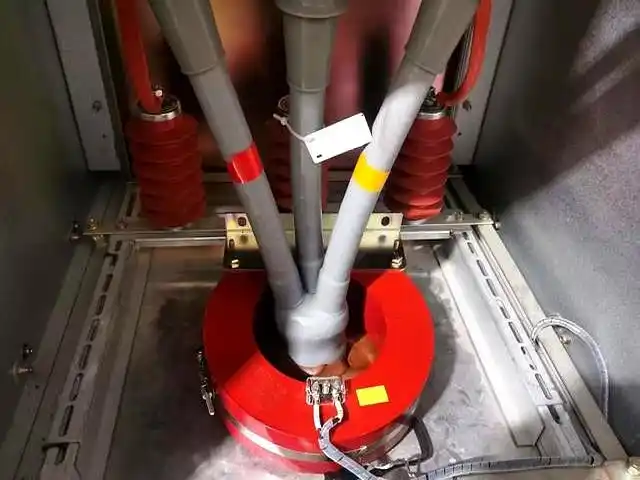
What Is a Generator Neutral Cubicle Current Transformer?
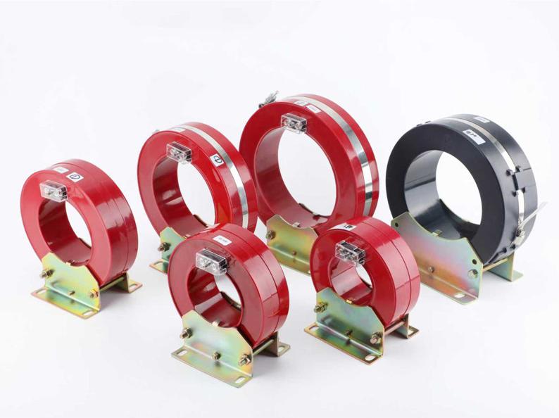
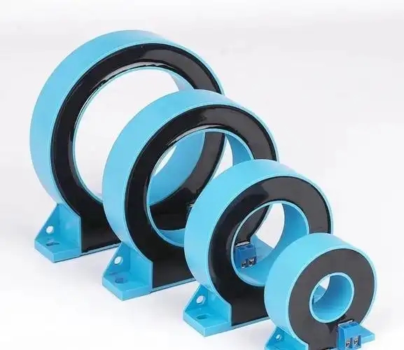
A generator neutral cubicle current transformer is a CT installed in the generator neutral grounding path. Its purpose is to measure neutral current so that protective relays can detect earth faults, leakage current, restricted earth fault conditions, and abnormal neutral current behavior.
It is commonly mounted around or in series with the connection between the generator neutral point and the grounding element. That grounding element may be a neutral grounding resistor, neutral grounding reactor, distribution transformer with resistor, or another earthing arrangement.
In simple terms, the CT tells the protection system what is happening in the neutral. The relay then decides whether the current represents a genuine earth fault, a transient, or a condition that should trip the machine.
The current transformer specification for generator neutral earthing cubicle therefore affects the performance of 64G, 51N, 50N, REF, and sensitive earth-fault functions, depending on the protection philosophy used.
How to Select a CT Ratio for a Generator Neutral Cubicle
The first principle is straightforward: the CT ratio must match the expected neutral current range, not the generator rated current on the phase side. That sounds obvious, but it is still the most common selection error in the field.
To choose the right ratio, start with the maximum neutral current that can flow during an earth fault. This current is determined mainly by the grounding method.
Then match that current to:
The relay secondary input rating, typically 1 A or 5 A.
The minimum relay pickup current required for reliable fault detection.
The desired sensitivity for low-level earth faults.
The expected transient and steady-state performance.
For example, if the neutral grounding resistor limits earth-fault current to 100 A primary, a CT ratio like 100/1 may be suitable. But if the grounding system limits fault current to only 10 A, a 100/1 CT is usually far too large for sensitive detection.
In that low-current case, ratios such as 10/1, 20/1, or 25/1 may be more realistic, depending on relay pickup and burden.
CT Ratio Selection for Generator Neutral Cubicle
CT ratio selection for generator neutral cubicle applications should always begin with the actual neutral fault current window. The objective is to create enough secondary current for the relay to detect low-level faults without sacrificing headroom for the maximum expected fault current.
A practical engineering rule is to aim for a secondary current near rated value when the neutral fault current reaches the designed grounding limit. This helps the relay operate with healthy signal strength while keeping the CT in a useful accuracy range.
Here is the logic engineers commonly use:
Determine the maximum continuous or short-time neutral fault current from the grounding design.
Select CT secondary rating, usually 1 A for improved burden performance over long leads.
Choose a ratio that allows low relay pickup at the smallest fault current of concern.
Verify that the selected class can deliver the necessary current into the total burden without unacceptable error or saturation.
Confirm coordination with relay settings and time-current characteristics.
For sensitive systems, lower ratios are generally better, provided thermal and short-time ratings remain adequate.
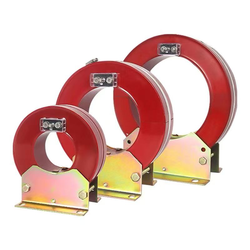
Generator Neutral Grounding Cubicle Current Transformer Sizing
Generator neutral grounding cubicle current transformer sizing depends on much more than one ratio number. It is the process of matching the CT’s electrical and mechanical capabilities to the real duty in the neutral circuit.
The main sizing inputs are:
Generator rated voltage and MVA.
Grounding type: solid, resistor, high-resistance, or reactor grounding.
Maximum earth-fault current in the neutral path.
Protection relay type and pickup sensitivity.
Secondary burden from relays and wiring.
Required accuracy class.
Short-time thermal and dynamic withstand duty.
Installation constraints inside the cubicle.
A 250 MW generator grounded through a resistor limiting current to 100 A does not need the same CT behavior as a smaller industrial 11 kV generator grounded at 10 A. Their protection tasks may look similar on the one-line diagram, but the measurement challenge is different.
Neutral CT sizing also needs to consider future maintainability. If the plant may later upgrade relays, modify grounding values, or add more protection functions, a slightly more capable CT may be justified.
Current Transformer Specification for Generator Neutral Earthing Cubicle
The current transformer specification for a generator neutral earthing cubicle should cover the following parameters clearly on the datasheet and purchase specification:
Primary current rating: based on maximum neutral fault current and application margin.
Secondary current rating: usually 1 A or 5 A; 1 A is often preferred where lead burden matters.
Accuracy class: such as 5P, 10P, PX/PS, or metering class as required.
Rated burden: sufficient for relay input plus leads plus terminals plus margin.
Accuracy limit factor or knee-point voltage: depending on class and scheme.
Short-time thermal current: must withstand fault duty for the specified duration.
Insulation level: matched to system voltage and cubicle arrangement.
Frequency: 50 Hz or 60 Hz.
Mounting type and window size: compatible with busbar, cable, or neutral conductor.
Environmental details: indoor, tropicalized, temperature range, pollution level.
Projects often fail at the interface between electrical design and procurement. The engineer may calculate the right ratio, but the procurement package may omit burden, knee-point, or terminal arrangement details. That can result in a physically installable CT that performs poorly in service.
Neutral Current Transformer Accuracy Class for Generators
The neutral current transformer accuracy class for generators must be selected according to the protection function, not just price or availability.
For many generator neutral cubicles, the CT is not used for revenue metering. It is used for protection, often sensitive protection. That changes the class selection priority.
Common classes include:
5P: protection class with composite error limits suitable for many standard protection duties.
10P: similar protection class but with less stringent error performance than 5P.
PX/PS: special protection class often selected when knee-point voltage, low leakage reactance, or defined winding resistance matters.
Metering classes: useful only if neutral current measurement for indication or monitoring is also required; usually not enough by themselves for sensitive protection.
For simple overcurrent neutral protection with moderate burden and clear fault currents, a 5P class CT may be adequate. For highly sensitive earth-fault or restricted earth-fault schemes, PX or PS class is often the safer choice because the protection engineer can specify exact electrical behavior.
One practical point from commissioning experience: if the relay scheme depends on distinguishing very low neutral current levels, the class decision should never be treated as a commodity choice. Errors and saturation at low current can lead to blind spots.
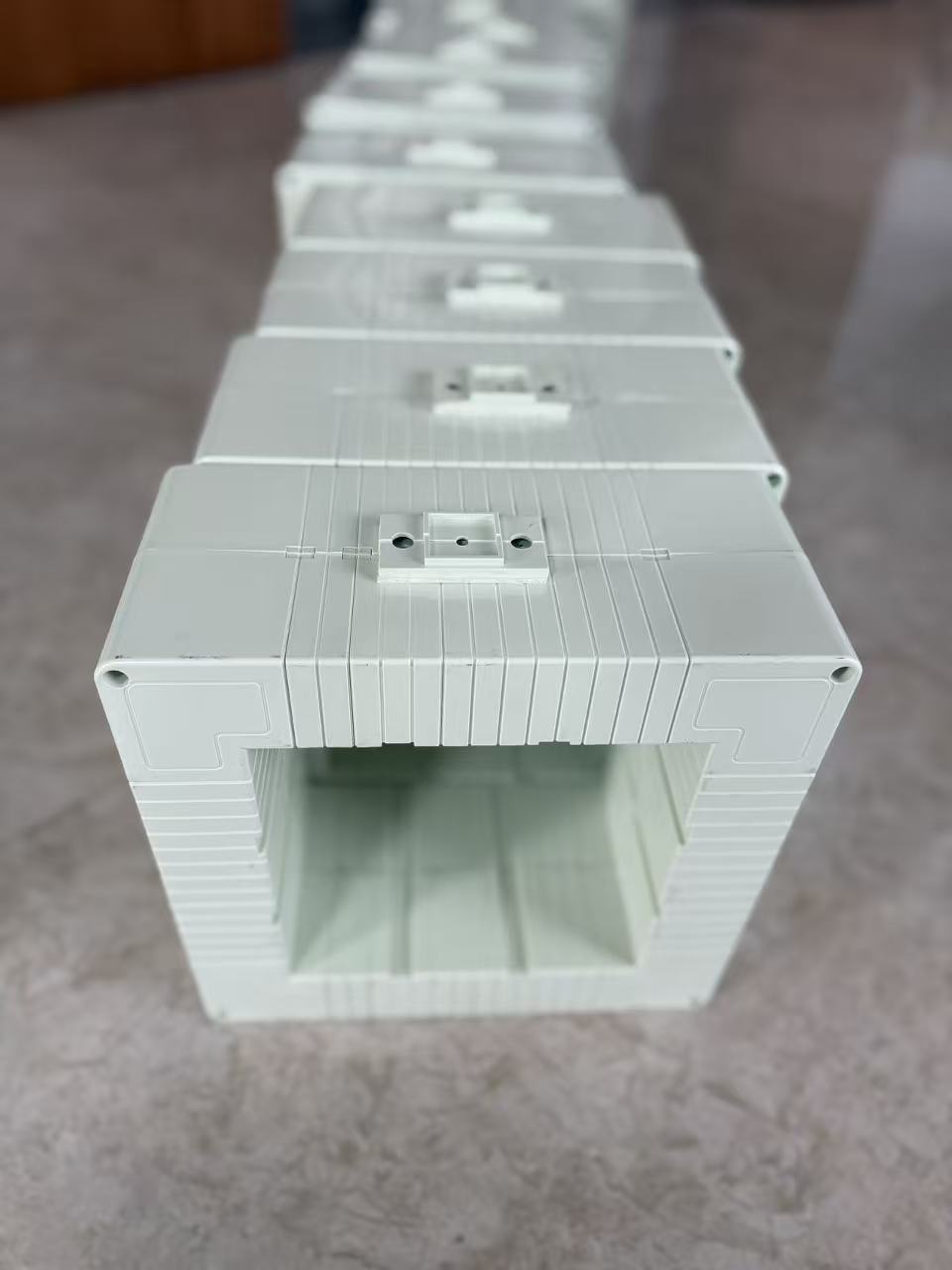
Generator Neutral Protection CT Burden Calculation
Generator neutral protection CT burden calculation is one of the most neglected parts of design. Yet burden directly affects whether the CT can deliver the required secondary current accurately to the relay.
Total burden is the sum of all secondary circuit loads seen by the CT. This usually includes:
Relay input burden.
Lead resistance of outgoing and return conductors.
Terminal blocks, test switches, links, and connectors.
Any auxiliary devices in the secondary circuit.
An engineering safety margin.
For a 1 A CT, even modest lead resistance can consume a noticeable share of the burden budget. That is why cable length and conductor size matter, especially in large generator rooms where the relay panel may be tens of meters away.
The burden in VA can be estimated using the secondary current and total impedance. A common simplified approach is:
Burden VA = I² × Z
Where I is the CT secondary rated current, and Z is the total secondary circuit impedance.
When using resistance values, the burden can be expressed as:
Burden VA = I² × R
for predominantly resistive circuits.
Engineers should also check whether the selected CT class performance is specified at the actual burden. A CT may meet class requirements at 2.5 VA but not at a higher real installed burden.
Key Selection Criteria Checklist
Before finalizing a neutral cubicle CT, verify the following points:
Ratio matched to maximum neutral fault current and minimum relay pickup.
Secondary rating chosen appropriately, often 1 A for lower lead burden.
Accuracy class suitable for protection objective.
Rated burden greater than actual calculated installed burden with margin.
ALF or FS appropriate for the scheme, or knee-point specified for PX/PS.
Short-time thermal current verified against fault duty and duration.
Insulation level suitable for the generator neutral cubicle arrangement.
Mechanical fit confirmed for conductor size, window opening, and mounting.
Environmental suitability checked for temperature, humidity, and enclosure conditions.
Standards compliance documented in the specification.
Step-by-Step CT Selection Process
A structured workflow reduces mistakes and makes approval easier across electrical design, protection engineering, and procurement teams.
Collect system data. Gather generator voltage, MVA, grounding method, grounding resistor or reactor values, and fault study results.
Define the protection objective. Confirm whether the CT serves 51N, 50N, 64G, REF, or a sensitive earth-fault scheme.
Determine neutral fault current. Calculate the maximum and minimum fault current levels that the relay must detect.
Select relay secondary basis. Choose 1 A or 5 A based on relay type and secondary wiring length.
Choose preliminary CT ratio. Match the primary current window to relay sensitivity.
Select accuracy class. Use 5P, 10P, PX/PS, or metering as required by the application.
Calculate actual burden. Include relay, cable, terminals, and margin.
Check CT capability. Verify rated burden, ALF, or knee-point against the scheme.
Confirm thermal and insulation ratings. Ensure the CT survives fault duty and fits the system environment.
Validate drawings and datasheet. Make sure the purchased item matches the calculations exactly.
This workflow is especially important for EPC projects, where errors often occur because the relay setting engineer and the cubicle manufacturer work from different assumptions.
Recommended CT Ratio Selection by Generator Neutral Grounding Method
| GROUNDING METHOD | TYPICAL NEUTRAL FAULT CURRENT | COMMON CT RATIO RANGE | SELECTION NOTES |
|---|---|---|---|
| Solid Grounding | High, often several hundred amps or more depending on system | 100/1 to 400/1 | Focus on thermal duty and relay coordination; sensitivity is usually less difficult. |
| Neutral Grounding Resistor (NGR) | 25 A to 400 A commonly used | 25/1, 50/1, 100/1, 200/1 | Match the ratio to the resistor-limited current and required pickup margin. |
| High-Resistance Grounding | 5 A to 25 A commonly used | 5/1, 10/1, 20/1, 25/1 | Low ratio is critical for sensitive fault detection; burden and class matter greatly. |
| Reactor Grounding | Varies widely by design | 20/1 to 200/1 | Use calculated fault current and transient behavior; verify relay scheme carefully. |
Neutral CT Accuracy Class and Application Match
| CT CLASS | BEST USE CASE | ADVANTAGES | LIMITATIONS |
|---|---|---|---|
| 5P | Standard generator neutral protection | Good protection accuracy, widely available | May be insufficient for very sensitive or highly engineered schemes |
| 10P | Basic overcurrent or less demanding protection | Economical, common in standard projects | Lower accuracy performance than 5P |
| PX/PS | REF, differential-related, and sensitive earth-fault duties | Specified knee-point and winding parameters, strong control over performance | Requires more detailed engineering and manufacturer coordination |
| Metering Class | Monitoring or indication only | Good low-current measurement for metering tasks | Not a substitute for protection class in fault detection schemes |
Sample Generator Neutral Protection CT Burden Calculation
| ITEM | BASIS | VALUE | CALCULATED BURDEN |
|---|---|---|---|
| Relay Input | Manufacturer data at 1 A secondary | 0.5 VA | 0.5 VA |
| Lead Length | 30 m one way, 60 m loop | Copper 2.5 mm² | 0.42 VA |
| Terminal Blocks/Test Switch | Project allowance | Equivalent resistance allowance | 0.15 VA |
| Auxiliary Margin | Engineering margin | 20% | 0.21 VA |
| Total | 1.28 VA |
The exact lead burden will vary with conductor size, temperature, and route length. The point is not the single number; the point is that burden must be calculated, not guessed.
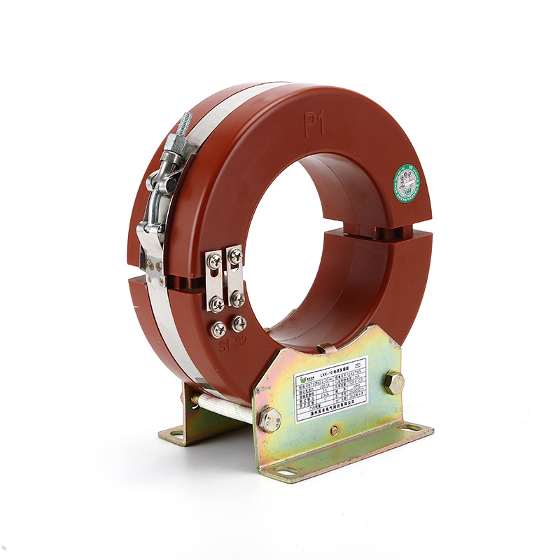
Real-World Example: 11 kV Generator with Neutral Grounding Resistor
Consider an 11 kV, 25 MW industrial generator connected through a neutral grounding resistor designed to limit earth-fault current to 100 A for 10 seconds. The protection philosophy includes neutral overcurrent and stator earth-fault protection.
The relay accepts a 1 A secondary input. The relay panel is installed 25 meters from the neutral cubicle, so the CT secondary loop length is about 50 meters.
A realistic selection process would be:
Maximum neutral fault current: 100 A primary.
Desired sensitivity: detect faults well below full NGR current.
Candidate CT ratio: 100/1.
Alternative under consideration: 200/1, rejected due to weaker low-current sensitivity.
Accuracy class: 5P20 or PX depending on relay scheme sophistication.
Burden result: approximately 1.2 VA to 1.5 VA including margin.
Selected rated burden: 5 VA minimum for comfortable margin.
Why is 100/1 better than 200/1 here? Because with 100 A primary fault current, the relay sees 1 A secondary at full NGR current. With a 200/1 ratio, it sees only 0.5 A secondary, which can reduce sensitivity to lower-level fault currents and make setting coordination less robust.
In one commissioning case from a process plant in Southeast Asia, an oversized neutral CT ratio caused the relay pickup to sit too close to background noise and system imbalance. The plant had to replace the CT after site testing because low-level earth faults could not be detected with enough confidence.
That kind of retrofit is exactly what careful design avoids.
Real-World Example: Sensitive Earth Fault Scheme in High-Resistance Grounded System
Now consider a smaller captive power generator using high-resistance grounding, where the maximum neutral fault current is only 10 A primary. The protection engineer wants a sensitive earth-fault scheme that detects faults at a small fraction of that value.
If a 100/1 CT were selected out of habit, a 2 A primary fault would produce only 0.02 A secondary. Many protection schemes would find that too small once burden, tolerance, and noise are considered.
A better approach might be:
CT ratio: 10/1 or 20/1.
Class: PX/PS or carefully selected 5P depending on relay design.
Secondary burden: minimized by using a nearby relay panel or larger cable cross-section.
Relay pickup: coordinated to detect low-level earth faults with margin above normal leakage current.
This is where the phrase neutral current transformer accuracy class for generators becomes more than a specification line. In high-resistance grounded systems, low fault current magnifies every CT weakness.
Engineers who work regularly on sensitive earth-fault applications know that ratio, class, and burden are tightly linked. A theoretically acceptable ratio can still fail in practice if the burden is too high or the class is not suitable for low-level performance.
Common CT Selection Errors in Generator Neutral Cubicles
Most field problems trace back to a short list of recurring mistakes.
Choosing the ratio based on generator full-load current instead of neutral fault current.
Using a 5 A secondary CT where long control cable runs make burden unnecessarily high.
Ignoring terminal block and test switch resistance in burden calculation.
Selecting 10P class for a sensitive scheme that really needs 5P or PX/PS.
Not verifying relay minimum pickup against the actual secondary current produced at low fault level.
Assuming any protection CT is fine for the neutral cubicle.
Under-specifying thermal withstand for the grounding resistor duty.
Failing to review manufacturer excitation data when special class CTs are required.
Another very practical error is documentation mismatch. The protection drawing may show 50/1, but the cubicle GA and purchase order may say 100/1. Unless someone checks all documents line by line, that mistake can reach site.
How to Verify the Final CT Specification Before Procurement
The final review stage should be formal, not casual. Before procurement, verify both engineering correctness and document consistency.
Use this review approach:
Check the grounding design. Confirm resistor or reactor value, fault current, and duty time.
Review relay settings philosophy. Make sure CT ratio and class support the intended pickup and operating times.
Recalculate burden independently. Do not rely only on catalog assumptions.
Confirm standards. Verify IEC or IEEE compliance required by the project.
Check insulation and thermal ratings. Ensure they fit the generator neutral installation.
Review manufacturer datasheets. For PX/PS, inspect knee-point voltage, winding resistance, and excitation curves.
Cross-check drawings. Single-line, schematics, cubicle drawings, BOM, and purchase specification must match.
Plan commissioning tests. Ensure the selected CT can be validated by injection and relay tests after installation.
Experienced teams also involve the relay engineer and the cubicle manufacturer in the same technical clarification cycle. That reduces the chance of a “correct component, wrong application” outcome.
For projects requiring dependable neutral protection performance, companies such as Weisho Electric are often evaluated not only on product supply but also on how well the technical specification aligns with the protection scheme and installation reality.
Featured Snippet Summary: How Do You Choose a Generator Neutral Cubicle CT?
You choose a generator neutral cubicle CT by matching the CT ratio to the expected neutral fault current set by the grounding method, then verifying that the selected accuracy class and burden performance support the relay’s protection objective. In practice, this means checking ratio, relay sensitivity, grounding resistor or reactor current, total secondary burden, thermal duty, and the required protection class such as 5P, 10P, or PX/PS before procurement.
FAQ
What CT ratio is best for a generator neutral cubicle?
There is no single universal ratio. The best CT ratio depends on the maximum and minimum neutral fault current, the grounding method, and the relay pickup sensitivity. A high-resistance grounded system may need a very low ratio such as 10/1 or 20/1, while an NGR-limited system at 100 A may suit 100/1. If the ratio is too high, the relay may lose sensitivity to low-level earth faults.
How do I size a current transformer for generator neutral grounding cubicle protection?
Start with the expected neutral earth-fault current from the grounding design. Then choose a ratio that gives the relay enough secondary current for dependable pickup, select an appropriate accuracy class, calculate the full CT burden including leads and terminals, and verify thermal, insulation, and mechanical requirements. In short, sizing is based on fault current, relay sensitivity, and secondary circuit burden rather than generator rated load current.
What accuracy class should a neutral current transformer for generators have?
For standard protection-only applications, 5P is often preferred over 10P because it offers tighter error performance. For very sensitive earth-fault or REF-type schemes, PX or PS class is often the better choice because it allows detailed control of knee-point voltage and winding characteristics. Metering class CTs should not be used alone where protection-class performance is required.
How is generator neutral protection CT burden calculated?
Generator neutral protection CT burden is the total VA load connected to the CT secondary circuit. It includes relay input burden, lead resistance for the full loop length, terminal blocks, test switches, and a safety margin. The burden is referred to the CT secondary and should always be checked against the CT rated burden and protection class performance.
Can I use a standard protection CT in a generator neutral earthing cubicle?
Yes, sometimes. A standard protection CT such as 5P may work well when the neutral fault current is clear, the relay scheme is straightforward, and the burden is modest. But in low-current or sensitive earth-fault applications, standard protection CTs may not be enough, and a low-ratio or PX/PS class CT may be required for dependable operation.
What happens if the neutral CT ratio is too high?
If the neutral CT ratio is too high, the secondary current becomes too small for a given primary fault current. That reduces relay sensitivity and can prevent detection of low-level earth faults. In practical terms, the protection may operate only for larger faults while smaller insulation failures remain undetected until they grow worse.
How do grounding resistor values affect CT selection?
The grounding resistor directly influences the maximum neutral fault current. A higher resistance usually means lower fault current, which in turn pushes the CT selection toward lower ratios and often better accuracy performance at low current. A lower fault current leaves less measurement margin, so burden and class become more critical.
Which standards apply to generator neutral cubicle current transformer specification?
Common references include IEC 61869 for instrument transformers, IEC 60034 for rotating electrical machines, IEEE C57.13 for instrument transformers, and the specific project protection relay standards or utility requirements. The correct standard set depends on region, owner preference, and whether the project follows IEC or IEEE design practice.
Conclusion: Best-Practice Approach to Generator Neutral CT Selection
The best-practice approach is simple in principle but disciplined in execution. Select the CT ratio from the actual neutral fault current, not from generator load current. Then verify the accuracy class, burden, thermal rating, insulation level, and relay coordination in one complete review.
The most important lesson is that neutral protection is often a low-current measurement problem. That means small design shortcuts can cause big protection gaps.
When engineers take time to validate CT ratio selection for generator neutral cubicle service, review generator neutral protection CT burden calculation, and choose the right neutral current transformer accuracy class for generators, the result is a protection system that is dependable, selective, and practical to commission.
For manufacturers and project teams alike, this is also where product quality matters. A well-specified neutral cubicle solution from a technically responsive supplier such as Weisho Electric can make the difference between a smooth commissioning cycle and a costly redesign after site tests.
CTA: Get Expert Help with Generator Neutral Cubicle CT Selection
If you are specifying a new generator package, upgrading a neutral grounding cubicle, or troubleshooting relay sensitivity issues, do not leave CT selection to guesswork. Get a project-specific review of ratio, class, burden, relay coordination, and grounding method before procurement.
Request an expert CT sizing review now for your generator neutral cubicle and make sure your protection scheme will operate when it matters most. A careful technical check today can prevent false trips, missed faults, equipment damage, and expensive site rework tomorrow.