A Step-Down Transformer Built for Amps, Not Volts
A low voltage, high current transformer is a step-down transformer that takes ordinary mains voltage, typically 380 V or 400 V, and delivers only a few volts on the secondary at currents of thousands of amps. The answer changes when the load needs direct current: the transformer then becomes the front end of a rectifier, and the rectifier sets much of the specification.
The reason to build such an unusual machine is heat. Resistive heating scales with the square of current, so a workpiece, a weld nugget or a busbar under test heats fastest when current is high. The voltage only needs to be high enough to push that current through a very low resistance. A spot weld between two steel sheets, a salt-bath electrode or a circuit-breaker contact has a resistance measured in micro-ohms or milliohms. A few volts are enough. Anything more would be wasted as extra losses or would need extra control to throttle back.
The low secondary voltage also makes high-current work at the load easier to manage, although it does not make it safe. Burns from hot conductors, molten metal and strong magnetic forces between conductors are still real hazards at these currents.
Why does the secondary have only a few turns?
The secondary of a low voltage, high current transformer has only a few turns, often a single turn, because voltage per winding follows the turns ratio. Fewer secondary turns give a lower output voltage, and because power in roughly equals power out, the current rises in the same proportion. That current is what forces the heavy copper construction.
In formula terms, U₁/U₂ = N₁/N₂. Put 400 V on a primary of 200 turns and a two-turn secondary gives about 4 V; a single turn gives about 2 V. The ampere-turns on both sides balance, so if the secondary carries 8,000 A on one turn, the primary carries only about 40 A on its 200 turns, plus a small magnetizing current.
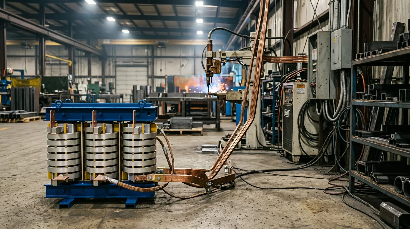
That arithmetic explains the look of these units. The primary is a conventional winding of many turns of relatively fine insulated wire or strip. The secondary is a heavy copper bar, a stack of copper foil, or, in many welding transformers, hollow copper tube with cooling water running through it. A single 8,000 A turn needs a cross-section that would be absurd anywhere else in a plant.
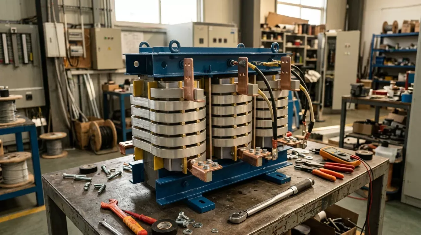
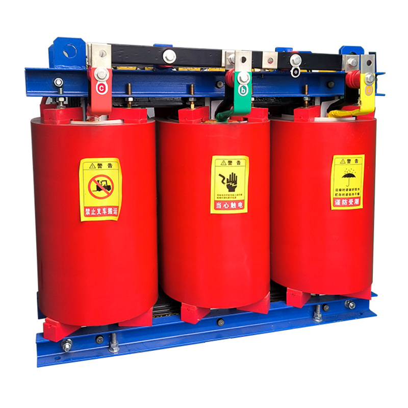
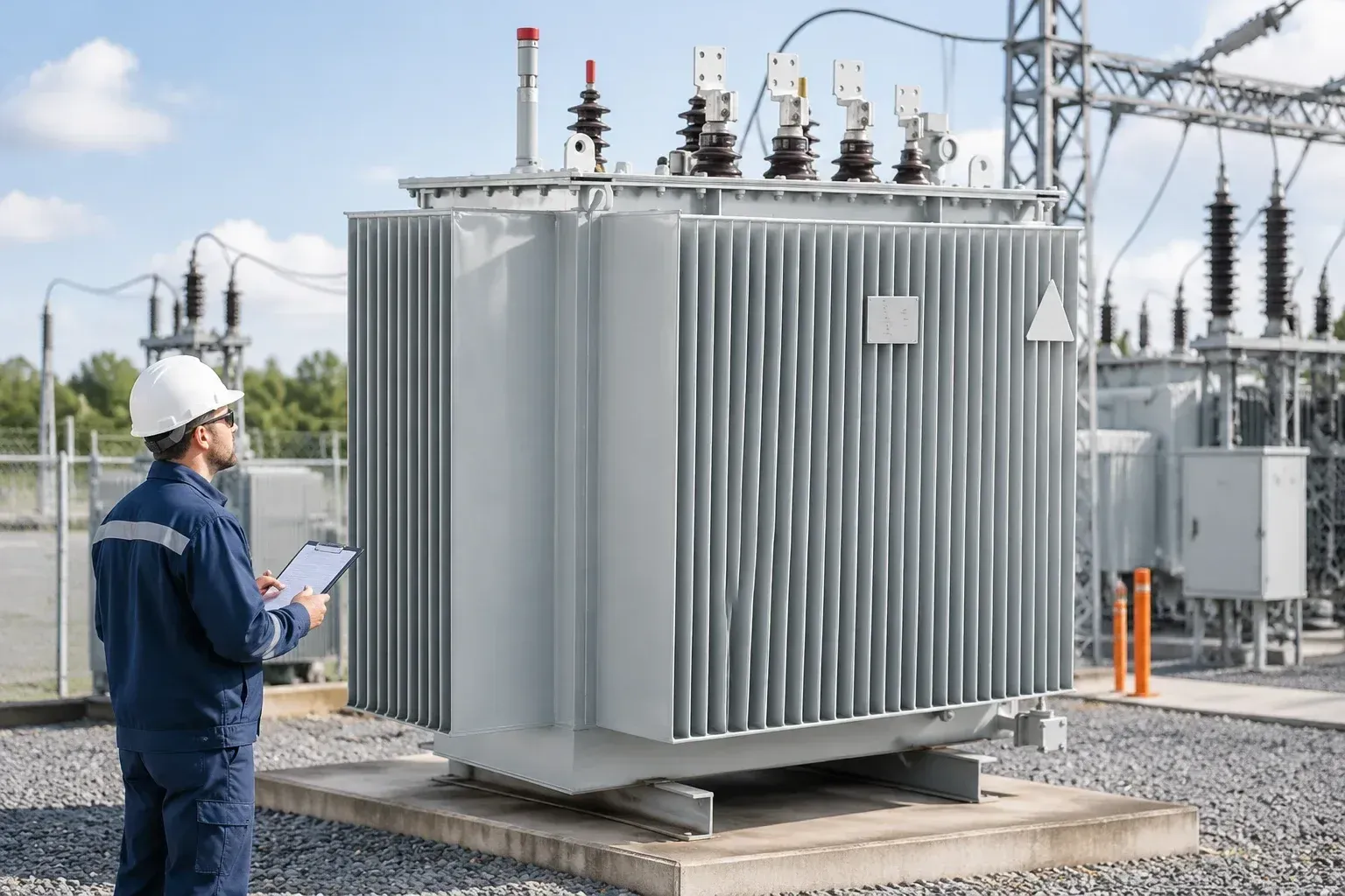
Most of these transformers are dry-type, meaning the windings are insulated with air, resin or varnish rather than immersed in oil. Cast-resin and vacuum-impregnated designs are common because the units often sit inside machines, close to people and hot work, where an oil-filled tank would be a fire and maintenance problem.
Typical Ratings and Specification Ranges
Low voltage high current transformer specifications cluster around a handful of supply voltages and a broad band of output currents. The figures below are typical ranges seen across welding, heating and test applications, not fixed catalogue values. Any real unit is designed to a specific load, and its datasheet takes priority over a general range.
| PARAMETER | TYPICAL VALUE OR RANGE |
|---|---|
| Input voltage (V) | 380–400 common; 220–240 or 480 by market |
| Input phase | Single-phase or three-phase |
| Supply frequency (Hz) | 50 or 60 |
| Output voltage (V) | Roughly 5–24 |
| Secondary current (A) | About 1,000 to over 10,000 |
| Secondary turns | Usually one to a few |
| Insulation thermal class | B, F or H |
| Cooling | Natural air, forced air or water |
| Duty type | Continuous, short-time or intermittent |
For most projects, the secondary current and the duty type in this table do more to set size and price than the input voltage does.
Two caveats apply. First, the output voltage figure is the open-circuit or rated-load voltage at the transformer terminals, not the voltage that reaches the workpiece. Conductors take their share. Second, the current figure means little without the duty attached to it. A 10,000 A rating at intermittent duty and a 10,000 A rating at continuous duty describe two very different machines. Medium-frequency welding systems, which run the transformer from an inverter at around 1 kHz, follow different size and weight rules from 50/60 Hz units and should be specified separately.
What Is a Low Voltage High Current Transformer Used For?
A low voltage high current transformer is used wherever a process needs large current through a low-resistance load: resistance welding, furnaces and heat treatment, high-current test benches, and the supply ahead of plating and electrolysis rectifiers. Each job loads the transformer differently, so the same nameplate current can call for very different designs.
Resistance welding: spot and seam
Resistance welding is the most common application. Body-in-white lines, appliance plants and wire-mesh makers use it, and the transformer sits inside the welding gun or the machine frame. It delivers short, repeated bursts of current that melt metal at the joint, then rests while the electrodes move. What you need is high peak current, stable output from weld to weld and a compact, often water-cooled unit. What to look for is the rating at the actual duty factor, the secondary voltage under load, and a cooling circuit sized for the line's cycle rate. Seam welding is harder on the transformer than spot welding because the current flows for longer stretches.
Furnaces, salt baths and metal heat treatment
Heat-treatment shops, forging plants and salt-bath operators run long heating cycles, sometimes for hours. Peak current matters less here than thermal stability: the transformer has to hold its rating for the whole cycle without its secondary creeping towards its temperature limit. Look for a continuous-duty rating, generous cooling and tap settings that let the operator adjust power as the load resistance changes with temperature.
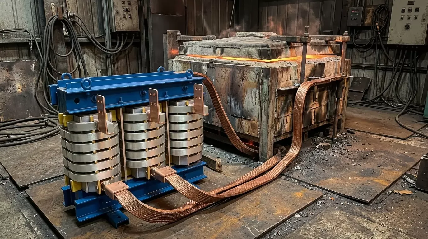
Test benches, electroplating and rectifier front-ends
Switchgear makers and test laboratories use these transformers for busbar temperature-rise tests and for high-current tests on circuit breakers and current transformers. Plating, anodizing and electrolysis plants use them ahead of rectifiers. Test benches need accurate, adjustable current and enough voltage headroom to drive long test loops. Rectifier duty needs a winding arrangement that suits the rectifier circuit and tolerates harmonic currents. In both cases, the duty is often continuous. A welding transformer moved onto a test bench is likely to be undersized thermally.
How It Differs from a Standard Distribution Transformer
A distribution transformer and a low voltage, high current transformer both step voltage down, and both work by the same electromagnetic induction. The similarity ends there. The table compares the two on the points that decide whether one could stand in for the other.
| CRITERION | DISTRIBUTION TRANSFORMER | LOW VOLTAGE, HIGH CURRENT TRANSFORMER |
|---|---|---|
| Secondary voltage | Typically 400 V class | Roughly 5–24 V |
| Secondary current | Hundreds to a few thousand A | Thousands to over 10,000 A |
| Secondary winding | Many turns of insulated conductor | One to a few turns of copper bar or foil |
| Cooling | Oil or air, mostly natural | Forced air or water common |
| Duty | Continuous, around the clock | Often short-time or intermittent |
| Typical load | Building and plant feeders | Welding, heating, test rigs |
The practical conclusion: if the load needs tens of volts or less at thousands of amps, a distribution transformer is the wrong starting point, however large its kVA rating.
The reason is geometry, not just numbers. A distribution transformer's secondary is built to supply 400 V to many feeders, with enough turns to hold that voltage. You cannot rewire it to give 8 V at 8,000 A; the secondary conductor would be far too small, and the terminal arrangement has nothing to carry that current. Putting a distribution transformer upstream and then dropping voltage further with a second stage only moves the problem.
Impedance is the other difference. Distribution transformers are designed with a short-circuit impedance that limits fault current on the network while keeping voltage regulation acceptable for ordinary loads. A high current secondary has to deliver its current into what is almost a short circuit by design. The internal impedance, and the impedance of the conductors attached to it, then decides how much current actually reaches the load. That is why the high-current design is tuned to its process, while a distribution transformer is tuned to the network.
Duty Cycle Decides More Than the Nameplate kVA
Many low voltage, high current transformers are not built to carry their rated current all the time. Welding transformers in particular are usually rated for intermittent duty, where current flows for part of each cycle and the windings cool during the rest. Run one at full rated current continuously and the secondary will overheat, often well before any protection notices.
Duty factor is the share of a reference period during which current flows. A weld that draws current for 0.2 seconds out of every second has a 20% duty factor. The reference period is defined by the rating standard or the manufacturer's datasheet, and it matters, because a unit rated over a short period may not tolerate the same total on-time grouped into one long block.
Because heating follows I²t, the thermally equivalent current changes with the square root of the duty factor. A transformer rated 10,000 A at 50% duty can carry roughly 10,000 × √0.5, or about 7,070 A, continuously. Run the same unit at 20% duty and the thermal limit rises to about 15,800 A. In practice the higher figure is rarely available, because the core, the secondary voltage and the mechanical bracing set other limits. The square-root rule tells you about heat. Nothing else.
Cooling method changes how much the copper can absorb. Natural air cooling suits lower currents and light duty. Forced air extends the range but adds fans, filters and noise. Water cooling, usually through hollow secondary conductors or cooled plates, removes heat directly from the copper and lets a compact unit carry very high current; it also makes the transformer depend on a water circuit that someone has to maintain.
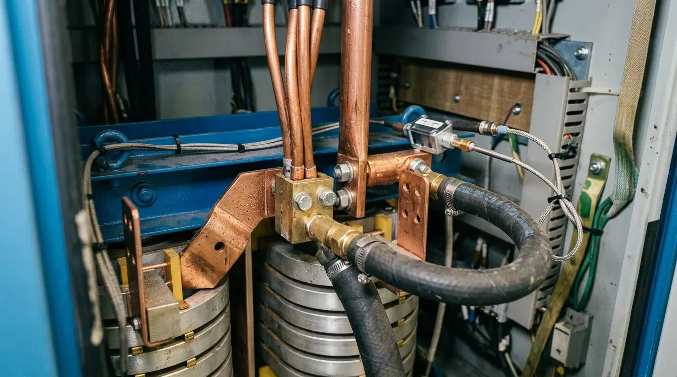
Thermal class sets the ceiling. Insulation classes defined in IEC 60085, such as Class F (155 °C) and Class H (180 °C), state the maximum temperature the insulation system can withstand over its expected life. A higher class gives margin, but it does not make a thermally undersized unit acceptable: insulation life still drops sharply when windings run hot for long periods. So compare units on duty factor first, then cooling, then thermal class.
High Current Low Voltage Transformer Sizing, Step by Step
Sizing works backwards. The load decides the current, the conductors decide how much voltage you have to add on top, and the duty decides how big the transformer must be to survive. Skip a step and the unit either fails to reach target current or runs hot.
Start from the current and voltage needed at the workpiece
Define the secondary current the process needs at the point of use: the weld current from the weld schedule, the test current from the test standard, or the heating current from the furnace design. Then find the voltage drop across the load itself at that current. For a resistive load this is simply current times load resistance; for a weld, the electrode and sheet stack resistance varies through the weld, so use the process supplier's figure or measurements from a comparable machine. A target of 8,000 A through a load that drops 3 V is the starting pair.
Add busbar, cable and contact losses
At these currents, conductors stop being negligible. Copper has a resistivity of roughly 0.0172 Ω·mm²/m at 20 °C. A 5 m loop of 1,000 mm² copper bar therefore has a DC resistance of about 86 µΩ, which at 8,000 A drops close to 0.7 V. Under alternating current the effective resistance rises because of skin and proximity effects (the skin depth in copper at 50 Hz is roughly 9 mm), and the loop's inductance adds reactive drop that can exceed the resistive part on a wide loop.
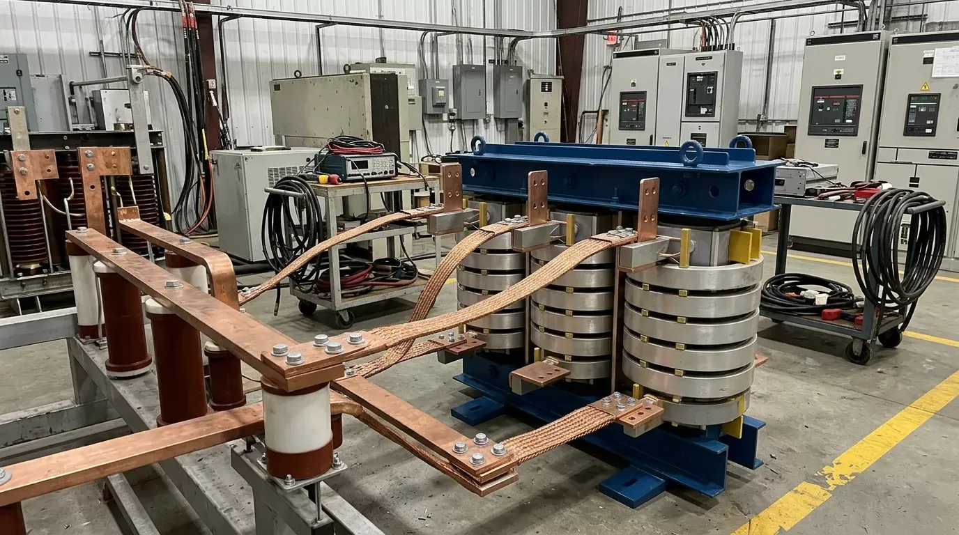
Joints add more. A bolted joint at 20 µΩ dissipates about 1.3 kW at 8,000 A and drops 0.16 V. Count every clamp, flexible lead and electrode holder. Keep the loop short and the go and return conductors close together; loop area drives inductance.
Convert to kVA at your real duty cycle and check impedance
Add the load drop and the conductor drop to get the required secondary voltage, then add margin for supply tolerance. If 3 V at the load plus 1.5 V in the loop gives 4.5 V, a rated secondary of about 5–6 V leaves headroom. Multiply by current to get apparent power: 6 V × 8,000 A is 48 kVA at the duty you specified. Convert that duty to the manufacturer's reference duty with the square-root rule before comparing quotes.
Last, check the short-circuit impedance. It sets how much the secondary voltage sags under load, which is regulation. A process that needs steady current, such as a test bench, tolerates less sag than a furnace with closed-loop control. Ask the manufacturer for the calculated secondary current at your actual loop impedance, not just the nameplate figure.
How to select a low voltage high current transformer for your line?
To select a low voltage high current transformer, confirm electrical fit first, mechanical and cooling fit second, and compliance third. That order matches how an engineer narrows the options and how a buyer avoids re-quoting. A unit that fits electrically but cannot be mounted, cooled or certified for your market will still fail the project.
Electrical fit
Start with the input supply: voltage, frequency, and whether you have single-phase or three-phase power at the machine. That decides the primary design and the current the plant must provide. Next, check that tap settings cover your adjustment range, since load resistance changes with tooling, temperature and part thickness, and taps are cheaper than a second transformer. Then the secondary current rating at your duty, and the regulation at your loop impedance. Finally, look at the power factor seen by the plant. High current loads with long loops are strongly inductive, and a poor power factor raises supply current, cable sizes and in some regions utility charges.
Mechanical fit and line integration
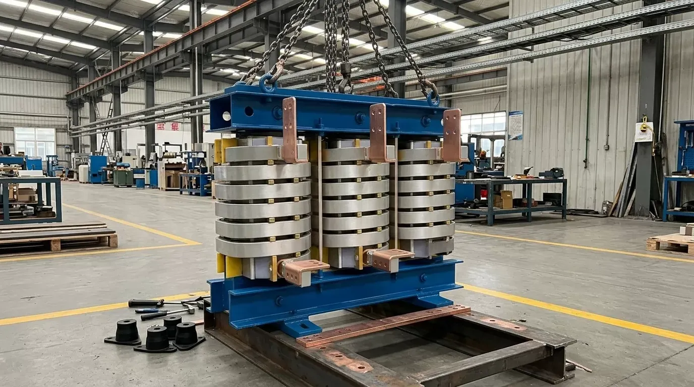
High-current terminals are the part most often redesigned late. Confirm footprint and weight, then the terminal and busbar layout: position, hole pattern, contact surface finish and the direction the conductors must leave the unit. For water-cooled units, specify flow rate, pressure, inlet temperature limit and fitting type; for air-cooled units, airflow clearance and ambient temperature. Mounting matters too. A transformer hung on a robot gun has weight and vibration limits; one bolted beside a furnace sees radiant heat; one on a test rig may be moved often and needs lifting points.
Safety and compliance
Pick the standard that matches the application. IEC 60076-11 covers dry-type power transformers. The IEC 61558 series covers safety of transformers and power supply units at lower ratings. For welding equipment, ISO 5826 sets general specifications for resistance welding transformers, and IEC 62135 covers safety of resistance welding equipment. Then add the market marking: in the European Union, CE marking under the Low Voltage Directive 2014/35/EU for equipment in its scope; in North America, the listing your customer or inspector requires. Temperature protection, such as thermal switches or sensors in the windings, should be part of the specification, not an option to add later.
A workable rule of thumb: if a transformer cannot show its secondary current at your duty, your loop impedance and your market's standard on one datasheet, it is not yet a candidate.
Mistakes That Overheat Secondaries and Blow Budgets
The most expensive error is getting duty wrong in either direction. Specify continuous duty for a spot-welding cell and you pay for copper and cooling that will never be used; the unit is also heavier on the gun. Specify intermittent duty for a temperature-rise test that runs for hours and the secondary overheats within the first test. The duty has to come from the process sheet or the test standard, not from an assumption about what similar machines use.
Conductor length is the second trap. A layout that moves the transformer a few metres further from the load, to clear a guard or a walkway, can add enough loop impedance to cut delivered current noticeably. The transformer itself is fine, but the process never reaches target. Fixing it after installation usually means a higher-voltage secondary, which means a new transformer.
Water-cooled units fail quietly when water quality is poor. Hard water leaves scale inside hollow conductors, which reduces flow and heat transfer; dirty water blocks small passages; conductive water can encourage corrosion and leakage currents. Most manufacturers state limits for hardness, conductivity, filtration and inlet temperature, and those limits belong in the plant's maintenance plan. A flow switch that stops the process when cooling fails costs little against a burnt secondary.
Loose high-current joints are another common cause of overheating. A joint that loosens through thermal cycling raises its resistance, heats further, oxidizes and loosens again. The failure often looks like a transformer fault, though the transformer itself is fine. Correct torque, clean contact surfaces, suitable plating, spring washers where specified, and periodic checks with a thermal camera or a micro-ohmmeter prevent most of it.
The last mistake is omitting temperature protection to save cost. A thermal switch or sensor embedded in the winding, wired into the machine control, is the only reliable way to stop a unit before insulation damage.
What drives price, lead time and total cost of ownership?
The price and lead time of a high current transformer for industrial applications are driven mainly by copper mass, custom secondary geometry, cooling, test scope and certification. Lifetime cost is driven by energy losses and maintenance. A cheaper unit with higher losses or awkward servicing can cost more over a few years than its purchase price saved.
Copper is usually the largest material cost, and secondary current sets how much of it there is. Copper prices move with the metal markets, so quotes are often valid for a short period or tied to a copper index. A custom secondary shape, such as an unusual terminal position, a hollow water-cooled conductor or a secondary built to fit inside a welding gun, adds design and tooling time. Standard frames with custom terminals are cheaper and faster than fully custom units.
Cooling adds parts and testing. A water-cooled unit needs pressure-tested circuits and fittings; a forced-air unit needs fans and possibly filters. Test scope matters more than many quotes show: routine tests are usually included, while a temperature-rise test at your duty or witnessed acceptance testing adds cost and calendar time. Certification work for a new market, if the design has not been certified before, can take longer than the manufacturing itself.
For lifetime cost, ask for no-load losses (the core, present whenever the unit is energized) and load losses (mostly copper, rising with the square of current). On a test bench energized all shift, no-load loss counts. On a welding line, load loss at the actual duty counts more. When you compare a quote from Weisho Electric with others, put both loss figures side by side at your duty, along with the cooling water or fan energy, and the estimated hours of maintenance for joints and cooling circuits per year.
A Complete RFQ Saves a Round of Re-Quotes
Most re-quotes happen because the first request gave current and voltage but left out the conditions that set size. A manufacturer can quote a nameplate. Quoting a working transformer needs the supply voltage and phase, the secondary current and voltage at the load, the duty factor with its reference period, the cooling method and available water or airflow, the dimensional envelope and terminal layout, the standards and market marking, and the test reports and acceptance tests you will require.
Sending a drawing or photo of the load loop, with conductor lengths and cross-sections, lets the manufacturer check regulation before quoting. For custom high current transformer manufacturers such as Weisho Electric, asking for two options, for example air-cooled and water-cooled at the same rating, is a fast way to see the cost of each cooling route. Two short checklists keep the exchange tight.
Before sending the RFQ
Secondary current, load voltage and duty factor are taken from the process or test standard.
Loop length, conductor size and number of joints are measured or drawn.
Required standards, marking and test reports are listed by name.
When the unit arrives
Nameplate rating, duty and thermal class match the order.
Test reports cover ratio, losses, impedance and insulation.
Terminals, cooling fittings and temperature sensors match the drawing.
Any mismatch found at delivery is far cheaper to settle before installation than after the line is commissioned.
FAQ
Can a high-current transformer run continuously at its rated current?
Only if it is rated for continuous duty. Many welding units are rated for intermittent duty, and their continuous capability is roughly the rated current times the square root of the rated duty factor, so check the datasheet before planning long runs.
Air-cooled or water-cooled: which do I need?
It depends on current, duty and space. Air cooling suits lower currents and light or moderate duty where space allows; water cooling suits compact units, very high currents or heavy duty, provided the plant can supply clean water at the stated flow and temperature.
How much voltage drop is acceptable on the secondary side?
It depends on the process. Agree a limit with the manufacturer by stating the minimum current you must reach at the load with your actual loop impedance; the manufacturer then designs secondary voltage and impedance to meet it, with margin for supply tolerance.
Is a single-phase or three-phase input better?
Three-phase, where it is available and the load is large. It balances the plant supply and suits rectified DC outputs. Single-phase units are simpler and often cheaper, but large single-phase loads unbalance the grid and draw higher line current.
What tests should I ask for before shipment?
Ratio, no-load and load losses, impedance, and insulation tests are the routine set. Add a temperature-rise test at your duty for new or modified designs, and a cooling-circuit pressure test for water-cooled units.
Where This Guidance Stops
The sizing method and ranges here fit 50/60 Hz dry-type units for welding, heating and test work. Medium-frequency welding transformers, transformers built into rectifier packages for large electrolysis plants, and units for hazardous locations follow their own standards and design rules, and the numbers above should not be carried over to them. Where the load resistance changes widely during the process, or the loop geometry is unusual, a calculation from the manufacturer based on your measured loop will replace the rough estimates used here.