"We need switchgear for a 20 kV feeder, so which panel do I actually quote?" Fix the network ratings first, then the insulation format, then the breaker and protection details, and compare suppliers only after that. Medium voltage vacuum switchgear is chosen through a chain of decisions, and each one narrows the next. If you take them out of order, two quotes that look identical can sit a full fault-rating step apart.
Which Medium Voltage Vacuum Switchgear Fits Your Distribution Network?
The right lineup matches your network's rated voltage and real fault level and suits the switchroom's internal arc layout. It should come in a format your crews can maintain and be backed by type tests your destination market accepts. Decide in five steps, in a fixed order, because each choice sets the limits for the next one.
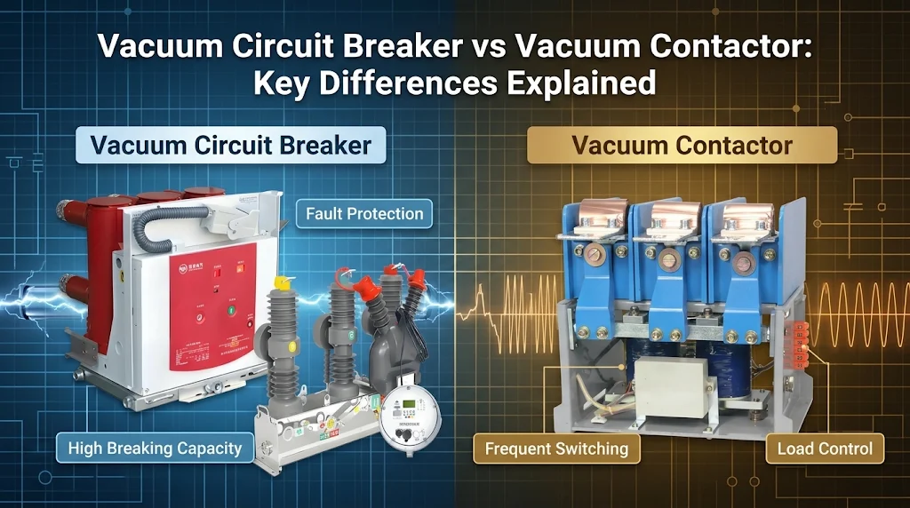
Vacuum switchgear is an assembly of switching, protection and metering devices in which load and fault currents are interrupted inside sealed vacuum interrupters. A vacuum interrupter is an evacuated ceramic chamber in which the arc dies out at current zero. The interrupter has become the default breaking technology at distribution voltages. The real choices are made around it.
https://www.weishoelec.com/product/metal-clad-switchgear/Confirm the voltage class from the system's nominal and maximum operating voltage.
Size the short-circuit rating to the fault level at the installation point, with headroom.
Choose the insulation format: air-insulated, gas-insulated or ring main unit.
Specify breaker endurance classes, internal arc class, mechanism, protection relays and communication.
Match compliance to the destination market and check the type-test evidence behind it.
Sellers rarely mention that most catalogue quotes skip steps one and two. They quote a standard panel at a standard rating and leave you to discover the mismatch. The steps above put the burden back where it belongs, on a specification you wrote yourself.
Rated Voltage Sets Every Other Choice: 12kV, 24kV and 40.5kV Classes
Rated voltage is the highest voltage the equipment is designed for, and it sits above the network's nominal voltage. A 10 kV or 11 kV system takes 12 kV equipment. A 13.8 kV, 15 kV or 20 kV system usually takes 24 kV equipment. Systems at 30–35 kV move into the 36 kV class under IEC, or 40.5 kV under the Chinese GB standards.
That is why 12kV and 24kV vacuum switchgear for distribution networks covers the bulk of industrial plants, commercial sites and utility secondary feeders. The 36/40.5 kV class appears mainly on larger primary feeders, on wind and solar collector systems, and in mining. It costs more per panel. It is also physically bigger, because the clearances grow with the insulation level.
The voltage class also fixes the dielectric test levels. These are the values a type-test report must show, so check them first when a report lands on your desk. The figures below are the common IEC 62271-1 values for 50 Hz systems. Some national standards, GB among them, specify higher power-frequency values.
| PARAMETER | 12 KV CLASS | 24 KV CLASS | 36 KV CLASS |
|---|---|---|---|
| Typical nominal system voltage (kV) | 10–11 | 13.8–22 | 30–35 |
| Rated voltage Ur (kV) | 12 | 24 | 36 |
| Power-frequency withstand, 1 min (kV) | 28 | 50 | 70 |
| Lightning impulse withstand, peak (kV) | 75 | 125 | 170 |
| Common rated normal currents (A) | 630–4000 | 630–2500 | 630–2500 |
Pick the class from your nominal voltage. Then make sure the test report shows at least these withstand values, and more if your local standard demands it.
One trade-off deserves a second look. Some buyers specify 24 kV gear on an 11 kV network "for future upgrades". This is sound only if a voltage upgrade is actually planned. Otherwise you pay for bigger panels and bigger cable boxes that will never be used.
Short-Circuit Current and Breaking Capacity Sizing
The fault level decides the price more than any other single parameter. It is also the figure most often copied from a catalogue instead of calculated. Rated short-circuit breaking current is the highest symmetrical fault current the circuit breaker must interrupt at rated voltage. Standard IEC values run in steps such as 16, 20, 25, 31.5 and 40 kA.
Sizing means matching the MV switchgear rated voltage and short-circuit current to the prospective fault current at the busbar where the gear will sit. The transformer rating and the neighbour's installation are the wrong references. A 25 kA lineup where 16 kA would do wastes money. A 16 kA lineup where the network can deliver 21 kA is a safety failure that nobody will notice until the day of the fault.
Getting the Fault Level From the Utility or Network Study
Ask the utility for the three-phase and single-phase fault levels at the point of connection, in kA or MVA. Ask for the X/R ratio as well, plus the earthing method of the system: solid, resistance, reactance, isolated or resonant. For an in-plant board, the figures come from a load-flow and short-circuit study under IEC 60909. That study should include motor contribution, because large motors feed current back into a fault for the first few cycles.
Then add headroom. Utilities reinforce their grids, add transformers in parallel and connect generation, and all of this raises fault levels over the life of the switchgear. Ask the utility in writing what the planned future fault level is. Where it lands close to a step boundary, take the next step up.
Short-Time Withstand, Duration and Peak Making Current
The rated short-time withstand current is the fault current the whole assembly must carry without damage for a stated time. That covers the busbars, the connections and the earthing switch, as well as the breaker. IEC 62271-1 prefers 1 s. Values of 3 s are common where upstream protection is slow, or where utilities set 3 s as their standard. A 3 s rating takes heavier busbars and supports, and the cost rises accordingly.
Peak withstand and making current follow from the short-circuit current. At 50 Hz IEC uses a factor of 2.5, so 25 kA becomes 62.5 kA peak. At 60 Hz the factor is 2.6. Networks with an unusually high X/R ratio, typically close to large generators, may need a higher factor. Check that the earthing switch carries a matching making capacity, because closing onto a live fault is exactly what it is rated for.
Air-Insulated, Gas-Insulated or Ring Main Unit?
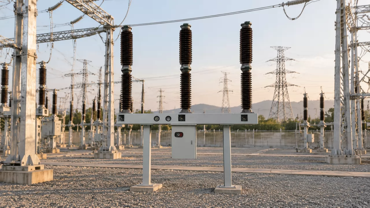
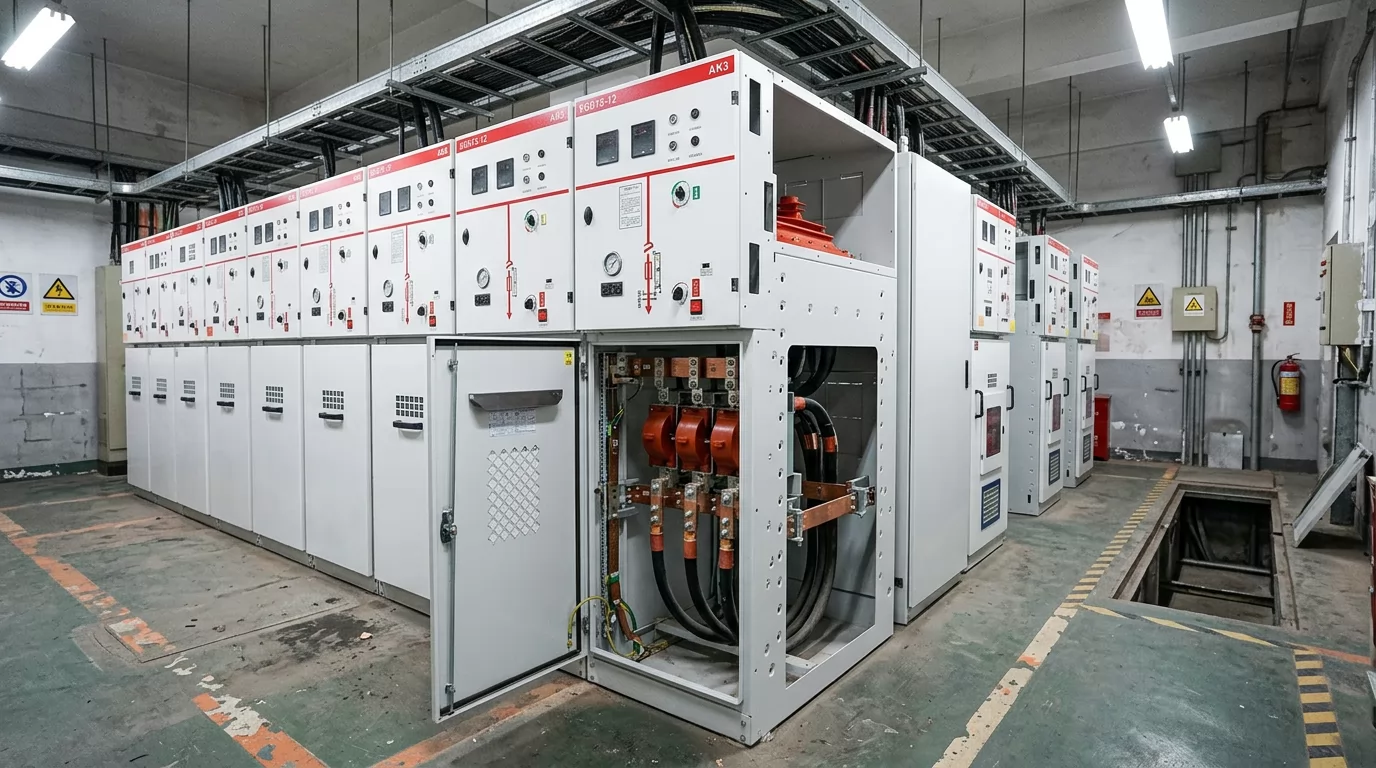
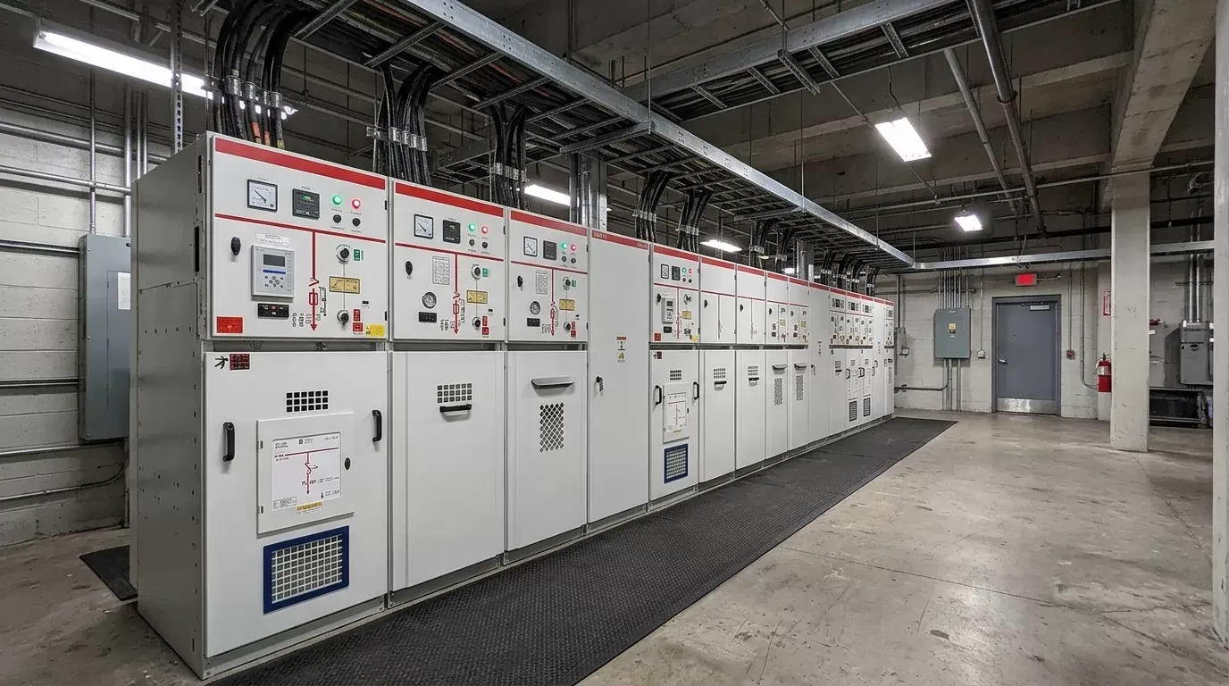
For most industrial and utility primary distribution, air-insulated metal-enclosed panels with withdrawable vacuum breakers remain the default. Gas-insulated switchgear earns its higher price where floor space is tight or the atmosphere is harsh. Ring main units suit secondary distribution with few feeders. In the EU, the restrictions on SF6 now shape the gas-insulated option.
Air-insulated switchgear (AIS) uses air as the main insulation between live parts. The breaker usually sits on a truck that racks out for maintenance. Gas-insulated switchgear (GIS) seals the live parts in a gas-filled tank, which makes the panels narrow and keeps them unaffected by dust, salt and moisture. A ring main unit (RMU) is a compact, factory-sealed unit, typically with two load-break switches for the ring cables and one breaker or fuse-switch for the transformer. Under IEC 62271-200 the old "metal-clad" class no longer exists as a formal term. Partition class PM, meaning metallic partitions between compartments, is the nearest equivalent. North American specifications still use the term, under IEEE C37.20.2.
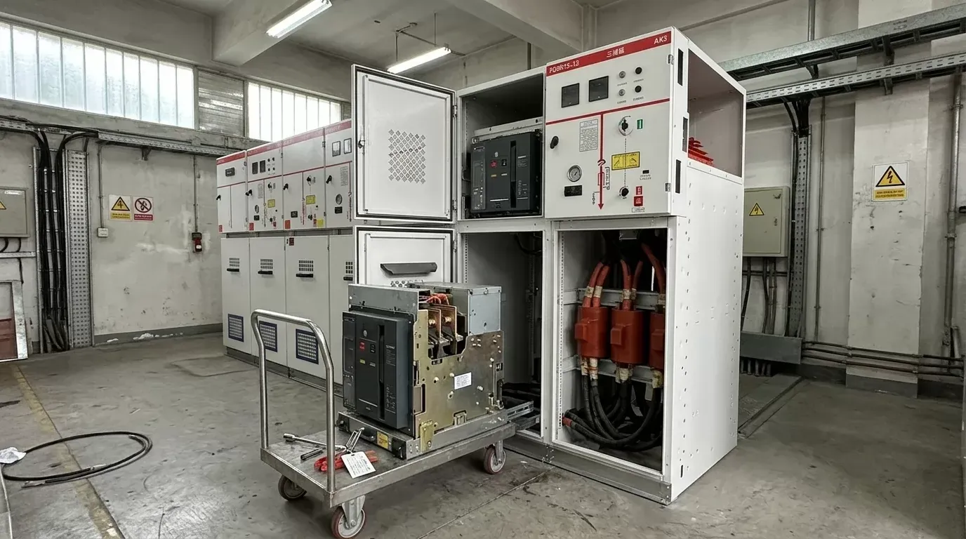
The gas question changed in the EU when the F-gas Regulation (EU) 2024/573 came into force. It bans SF6 in new MV switchgear in stages, starting with equipment up to 24 kV from 1 January 2026 and extending to 52 kV from 1 January 2030, with limited exceptions. Demand has shifted toward vacuum breaking combined with air, dry air or alternative-gas insulation. If your equipment ships to the EU, ask exactly which gas is in the tank and what the declared global warming potential is.
| CRITERION | AIR-INSULATED (AIS) | GAS-INSULATED (GIS) | RING MAIN UNIT |
|---|---|---|---|
| Footprint | Largest | Compact | Smallest |
| Breaker maintenance access | Withdrawable, easy | Sealed tank, limited | Sealed, minimal |
| Extending the lineup later | Straightforward | Needs matching coupling | Only extendable versions |
| Dust, salt, humidity tolerance | Needs clean room | High | High |
| Insulating-gas regulation exposure | None | Depends on gas used | Depends on gas used |
| Suits | Plant main boards, utility primaries | Cramped or harsh sites | Ring feeders, transformer stations |
If you have the floor space and a clean room, choose AIS. Move to GIS or an RMU only when space or environment rules AIS out.
Vacuum Circuit Breaker Switchgear Selection: The Criteria That Decide the Order
Two quotes with the same voltage, the same kA and the same panel count can still hide very different equipment. The gap shows up in the breaker classes, in the arc testing and in what is bolted to the door. Vacuum circuit breaker switchgear selection comes down to a handful of criteria. They are listed here in the order they usually decide the outcome.
The internal arc classification comes first. It is fixed by the room you already have, so a mismatch is often impossible to fix later. Breaker endurance follows, because one capacitor bank or one motor that starts many times a day changes the class you need. Protection and communication come next. A relay that will not talk to your SCADA is a commissioning delay waiting to happen. The mechanism type and interlocking are last. They matter, but most offers handle them adequately.
The rule of thumb: if a quote does not state the IAC rating and the E/M/C classes explicitly, treat it as incomplete and send it back.
Breaker Ratings: Mechanical and Electrical Endurance Classes
IEC 62271-100 is the standard for AC circuit breakers. It defines the classes that separate a commodity breaker from one built for heavy duty. Mechanical class M1 means 2,000 operations. M2 means 10,000 operations, and is the class you want for frequent switching. Electrical class E2 means the interrupting parts need no maintenance during the expected service life in distribution duty. E1 is the basic class.
The capacitive switching classes are C1 and C2. C1 indicates a low probability of restrike when the breaker switches capacitive current, and C2 a very low probability. Restrikes during capacitor bank switching cause overvoltages that damage cables and the capacitors themselves. So a feeder supplying power factor correction or a harmonic filter should carry C2, ideally together with M2 and E2. The same goes for arc furnace supplies and motors started many times a shift. Check the numbers as well as the class letters. The datasheet should list the operation counts, the rated operating sequence (for example O–0.3 s–CO–3 min–CO) and the capacitive currents tested.
Internal Arc Classification and Compartment Design
Internal arc classification (IAC) under IEC 62271-200 states that the enclosure protects people from an arc fault inside it. The rating is tied to a specific accessibility type, test current and duration. A rating of "IAC AFLR 25 kA 1 s" means accessibility type A, for authorised personnel only, with protection proven on the front, lateral and rear sides at 25 kA for one second.
The catch is that the rating holds only if the room matches the test arrangement. A panel tested as AFL with a rear wall assumes a wall behind it at a set distance. If you set the panel freestanding, with a walkway behind, you have left the tested condition. Arc gases need a path out of the room as well, which may be through ducts, absorbers or a vent to the outside. Ask for the venting arrangement drawing with the room dimensions marked on it.
Two other classes describe how the panel behaves in service. Loss of service continuity (LSC) tells you what stays live when one compartment is opened. With LSC2A, the busbars and other functional units stay energised when one compartment is opened. LSC2B goes further and keeps the cable compartment of the opened unit energised as well. Partition class PM (metallic) or PI (insulating) describes the barriers. Plants that cannot shut the whole board down for maintenance should specify LSC2B with PM.
Operating Mechanism, Protection and Communication
Most distribution breakers use a motor-charged spring mechanism. It is proven and can be repaired in the field, and most electricians already know it. Magnetic actuator mechanisms use far fewer moving parts and are often rated for very high operation counts. That makes them attractive for frequent switching, but repair depends more heavily on the original supplier. Ask about spares for either type before you commit.
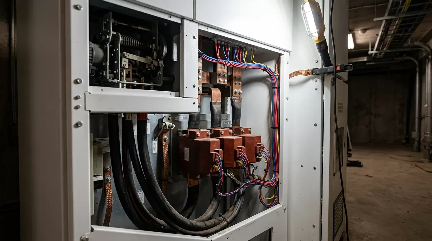
Name the relay brand and model range in the specification, or the supplier will choose one for you. Where the board connects to a substation automation system, require IEC 61850 with a stated edition. Ask whether GOOSE messaging will be used for interlocking and who supplies the configuration files. Remote racking and remote operation keep operators out of the arc zone and deserve a line in the RFQ. The interlocks between the breaker, the earthing switch and the doors should be mechanical, with optional key interlocks to the upstream transformer.
Compliance Depends on the Destination Market: IEC 62271-200, IEEE C37 and Local Approvals
Three type-test regimes are often blurred together, and they are separate. IEC 62271-200 covers the AC metal-enclosed switchgear assembly, including temperature rise, dielectric tests, short-time withstand, internal arc and ingress protection. IEC 62271-100 covers the circuit breaker on its own. For North America, IEEE C37.20.2 covers metal-clad switchgear. The breakers fall under the IEEE C37.04, C37.06 and C37.09 family, and arc testing follows IEEE C37.20.7. An IEC-certified lineup is not automatically acceptable in the US or Canada, and the reverse is also true.
IEC 62271-200 compliance is proven by type-test reports. A declaration of conformity does not prove it. Read the report itself. Check that it comes from an independent, accredited laboratory, such as a member of the Short-Circuit Testing Liaison (STL) or a lab accredited to ISO/IEC 17025. Then check that the tested object matches what you are buying. The panel width, the busbar size, the breaker model, the rated current and the IAC arrangement must all line up. A report on a 1,250 A, 800 mm panel does not prove the performance of a 2,500 A, 600 mm variant.
Many utilities then layer their own approval on top. That may mean a product registration, a witness test or a listing on an approved-supplier list, which can take longer than manufacturing. Ask the utility early whether the model you are considering is already on their list. If it is not, find out how long qualification takes.
Site Conditions and Derating
IEC 62271-1 defines normal service conditions. These cover an indoor ambient up to 40 °C, with a 24-hour average no higher than 35 °C, an altitude up to 1,000 m, and limited humidity and pollution. A site outside those limits needs corrections.
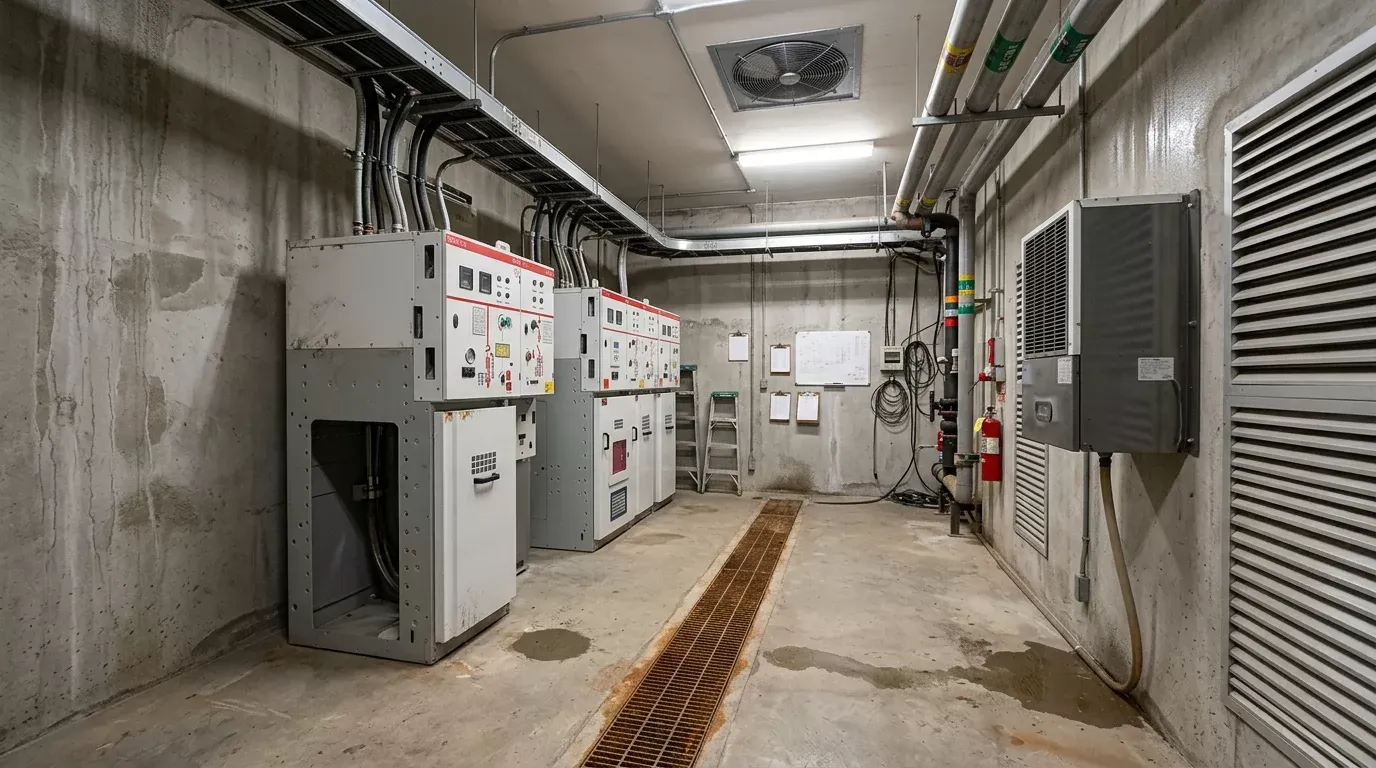
Above roughly 1,000 m, the thinner air lowers dielectric strength, so the insulation level is corrected upward or a higher voltage class is chosen. A hot switchroom reduces the current a panel can carry. A 1,250 A panel at 50 °C may carry noticeably less than 1,250 A unless it was designed and tested for that temperature. Coastal and dusty sites call for a pollution severity assessment, guided by IEC TS 60815, and anti-condensation heaters. Seismic zones need qualification evidence, under IEC 62271-210 or IEEE 693 where utilities require it.
Send the following with the enquiry: altitude, minimum and maximum ambient, humidity, pollution level, seismic zone, and whether the room is air-conditioned.
What Drives Cost, Lead Time and Total Cost of Ownership?
Price follows five things. They are, roughly in order, the fault rating, the insulation format, the relay specification, the metering class and the number of panels. A lead time is predictable only for a lineup built from type-tested standard modules. Over the service life, maintenance intervals, spare-part support and interrupter endurance often outweigh the difference in the initial quote.
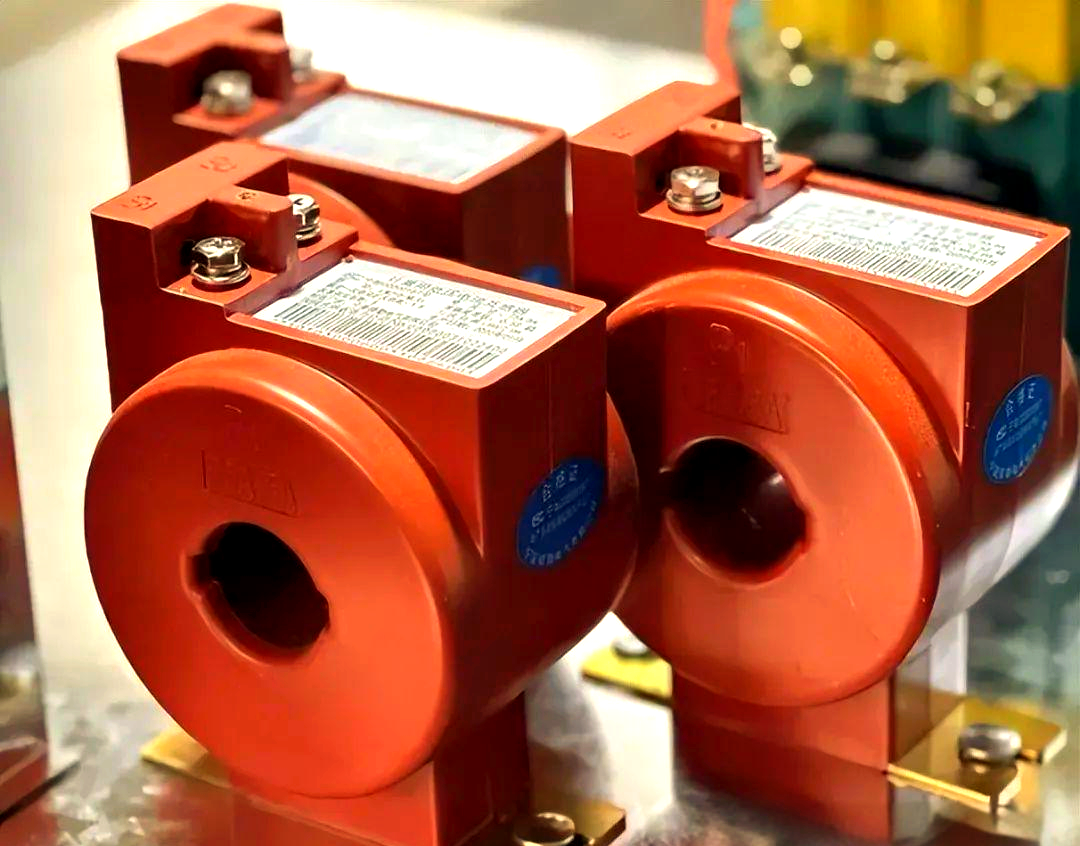
Each step up in kA brings heavier busbars, larger breakers and sometimes a different panel frame. GIS costs more per panel than AIS at the same rating. Relays with full IEC 61850 integration, differential protection or arc-flash detection add more than most buyers expect. Revenue-class metering CTs, which must be certified to the utility's accuracy class, add both cost and paperwork.
Lead time grows with every deviation from the standard. A non-standard panel width, an unusual cable entry, a busbar coupling to an existing lineup or a customer-specific relay scheme each mean engineering hours and sometimes a new drawing approval cycle. Standard lineups typically ship within weeks to a few months. Customised layouts usually take longer, and drawing approval delays on your side count toward that time.
Total cost of ownership tilts the comparison. Vacuum interrupters with E2 and M2 ratings need little attention beyond periodic inspection, mechanism lubrication and contact-wear checks. Ask three things in writing. First, the recommended maintenance interval. Second, how long spare breakers, mechanisms and relays will be supplied after the model is discontinued. Third, whether interrupter wear can be measured on site. A cheaper board that needs an outage every two years can cost more than the dearer quote by the end of its life.
Factory Tests and Documents Reveal How Reliable a Supplier Is
Every panel that leaves the factory should pass routine tests under IEC 62271-200. These include a power-frequency dielectric test on the main circuit, measurement of main-circuit resistance, mechanical operation tests, checks of auxiliary and control circuits, and a gas-tightness check on sealed units. A factory acceptance test (FAT) is the session in which you or your inspector watch selected tests, inspect the build and sign the record before shipment.
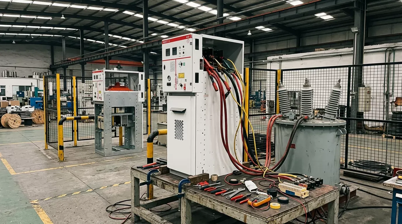
Ask Weisho Electric, or any other supplier on your shortlist, for a blank routine-test report and the FAT procedure before you place the order. The form shows how disciplined the shop floor is. It shows the measured values, the tolerances and who signs, and it indicates whether the test sequence is fixed or improvised.
| STAGE | WHAT IS CHECKED | WHO SIGNS OFF |
|---|---|---|
| Drawing approval | Single-line diagram, layout, wiring schematics | Buyer's engineer |
| Routine tests | Dielectric, contact resistance, mechanical operations | Supplier QC |
| FAT witness | Interlocks, relay injection, control wiring | Buyer or third-party inspector |
| Pre-shipment inspection | Nameplates, accessories, packing, desiccant | Buyer's inspector |
| Site acceptance | Damage check, insulation resistance, functional test | Commissioning engineer |
If you can attend only one stage, choose the FAT. Faults found in the factory cost hours to fix, while the same faults found on site cost weeks.
The documentation pack should include the type-test reports, the routine-test certificates per panel, as-built drawings, relay setting files, the manual, the spare-parts list, and CT/VT test sheets. For export, specify seaworthy crating, vapour-barrier wrapping with desiccant, and tilt and shock indicators on each crate. A tripped indicator on arrival is your evidence for the insurance claim.
Specification Mistakes That Show Up at Commissioning
The most expensive errors are made at the desk and found on site. One common error is to set the short-circuit rating from the transformer size instead of the calculated fault level. Another is to order an IAC rating whose tested arrangement does not match the room, so the arc protection is void before the first switching operation.
Cable termination details are often missing. The specification may not give the number of cables per phase, the conductor size or the termination type, and the cable compartment then turns out too shallow for the actual cables. Relay settings are frequently left "to be decided by others", so nobody loads them and the first energisation is delayed. Extensions to existing boards fail when the new panel's busbar height, cross-section or coupling system does not match the old one. Ask for the existing lineup's drawings before you ask for a price.
Run This Checklist Before You Send the RFQ
Before the RFQ goes out, work through the points below and fill each one in on a single specification sheet. A supplier such as Weisho Electric can then answer it line by line rather than guessing.
State the nominal and maximum system voltage, the frequency and the system earthing method.
Enter the calculated fault level, the X/R ratio and the utility's planned future fault level.
Specify the rated voltage, the busbar and feeder rated currents, and the short-time withstand current with its duration.
Select the format (AIS, GIS or RMU) and the insulating medium, stating the gas if one is used.
Define the breaker classes M2/E2/C2 per feeder where the duty calls for them.
Specify the IAC rating, the LSC category and the partition class, and attach the room layout.
Name the relay brand, the protection functions, the IEC 61850 edition and the metering accuracy class.
List the cable sizes, the number of cables per phase and the termination type for each feeder.
Request type-test reports from accredited labs that match the offered configuration.
Add the site conditions: altitude, ambient range, humidity, pollution and seismic zone.
Define the FAT scope, the witness points and the documentation pack.
Specify export packing, desiccant and shock indicators.
Ask for recommended spares, the spare-supply period and the warranty terms in writing.
A sheet completed this way makes the quotes directly comparable. A supplier who skips lines in the reply has told you something useful.
Questions Often Asked About MV Vacuum Switchgear
Can 12 kV switchgear be used on an 11 kV network with future upgrade plans?
Yes for 11 kV, since 12 kV equipment is rated for it. A planned move to 20 kV or 22 kV needs 24 kV equipment from the start. Changing the voltage class later means replacing the board.
How often do vacuum interrupters need replacing in distribution duty?
Rarely. In normal distribution duty an E2/M2 interrupter often lasts the life of the panel. Replacement is driven by contact wear after many fault interruptions, or by a failed vacuum integrity check. The manufacturer's wear curve or wear indicator tells you when it is due.
When does a ring main unit make more sense than a metal-clad lineup for primary distribution substation equipment?
Choose an RMU for compact transformer stations and ring feeders with few circuits and moderate fault levels. A substation with many outgoing feeders, high currents, or a need for withdrawable breakers and full protection per feeder belongs on a metal-clad lineup.
How do SF6 restrictions affect existing gas-insulated units already installed?
Under (EU) 2024/573, installed equipment can generally stay in service and be maintained. The restrictions target new equipment placed on the market, while servicing and end-of-life gas recovery must still follow the regulation's handling rules.
Is a type-test report from another factory's panel acceptable for the same design?
Sometimes, and it is worth pressing on. Licensed designs built under the licensor's control may legitimately share reports. Otherwise, the report covers the object tested, made where it was made. Ask for a licence agreement or production audit evidence, and be wary of reports in which a different company name has been pasted in.
The Short Version: Ratings First, Format Second, Supplier Last
Fix the voltage class and the fault level from network data, choose the format to suit the room and the regulations, and only then line up suppliers against identical requirements. The first document to prepare is a completed specification sheet built from the checklist, because every quote you receive will be only as good as that sheet. Specify the gear for your network, never for the catalogue.