This guide is for protection engineers and substation designers, as well as plant maintenance managers, who specify or review power transformer protection; if you only need to know what a transformer does, skip it.
Protection splits into three groups: electrical relays, mechanical and gas devices, and thermal monitoring. The right mix depends on rating and location, as well as on what a failure would cost you.
How Is a Power Transformer Protected Against Faults?
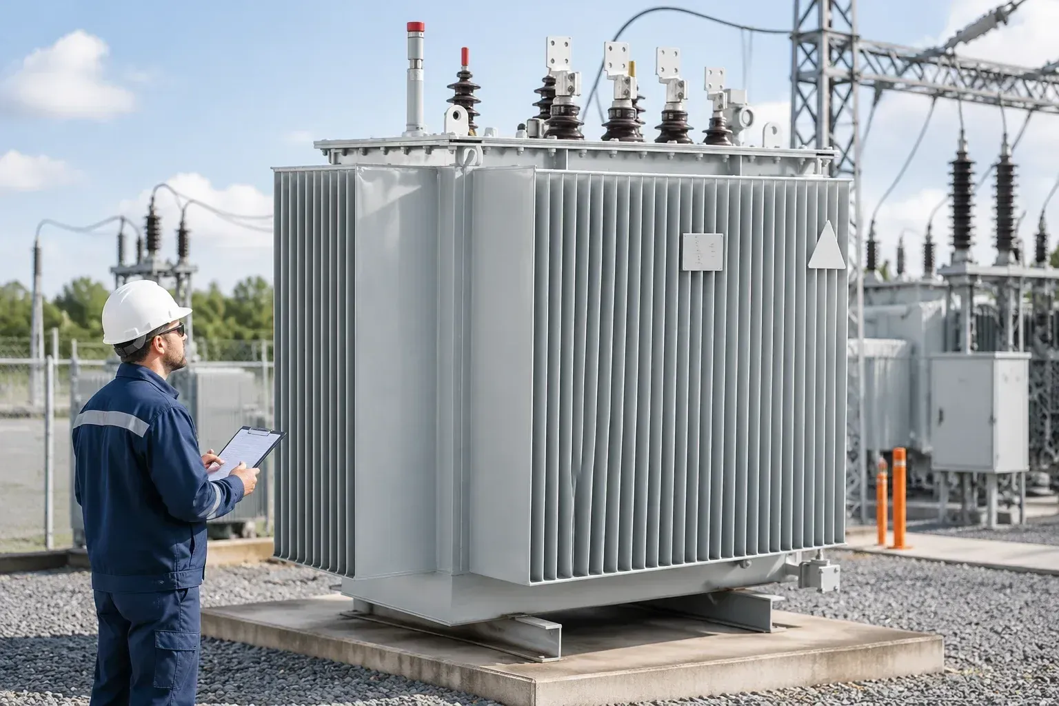
A power transformer is protected through layers: electrical relays for winding and terminal faults, mechanical devices for faults inside the oil tank, and thermal and pressure devices for slow or abnormal conditions. No single device covers all three. Each layer exists because the others are blind to something.
Electrical relays act on current. A differential relay compares what enters and leaves the windings and trips quickly when the two disagree. An overcurrent relay sits behind it as backup, and it also sees faults on the connected network that the differential scheme deliberately ignores.
Mechanical devices respond to what the fault does to the oil. A Buchholz relay, for instance, collects gas or senses an oil surge in the pipe to the conservator. It can catch a small insulation problem long before enough current flows to move a relay.
Thermal and pressure devices cover the slow and the violent. Winding and oil temperature indicators warn about overload and cooling failure, while pressure relief valves and sudden pressure relays limit the damage when an arc builds pressure in the tank.
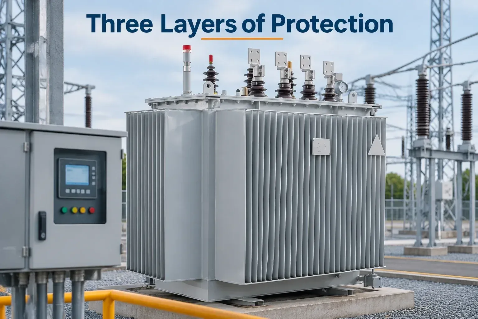
The trade-off is cost against consequence. A small distribution unit may justify little more than fuses, whereas a large unit feeding a critical load usually gets all three layers, often duplicated. The sections below take each layer in turn and then fit them to real situations.
Which Types of Transformer Protection Relays Do You Actually Need?
Four things decide the answer: rating, oil or dry construction, the consequence of an outage, and who maintains the relays. Most schemes start from a short core and add to it.
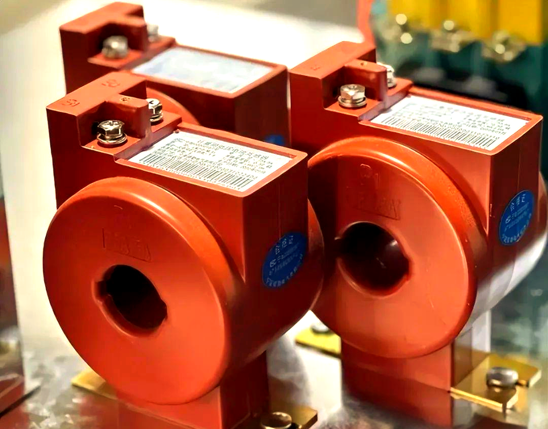
The core set. A differential relay (device 87T) for winding and terminal faults, an overcurrent relay for backup, and a gas or pressure device on every oil-filled unit. Drop any of the three and a whole class of fault goes unseen.
Rating. Small units often get by with overcurrent alone or fuses. As MVA climbs, a differential relay becomes the primary protection, because overcurrent settings cannot be both sensitive enough for internal faults and tolerant of load and inrush.
Criticality. Where an outage stops a process or a feeder with no alternative supply, add a second relay from a different manufacturer or with different principles, plus thermal monitoring and sudden pressure detection.
Maintenance capacity. A relay nobody tests or reads is a liability. Simple electromechanical or basic numerical devices suit sites with limited protection staff; complex multifunction relays pay off only if someone owns the settings.
| Device or function | Fault type covered | Speed | Typical application | Main limitation |
|---|---|---|---|---|
| Differential (87T) | Winding and terminal faults, in-zone short circuits | Fast, typically a few cycles | Medium and large power transformers | Needs inrush restraint and well-matched CTs |
| Overcurrent (50/51) | External short circuits, through-faults, overload backup | Delayed, set for coordination | All ratings, as backup | Slow and insensitive to minor internal faults |
| Buchholz relay | Gas from incipient faults, oil surge from severe ones | Alarm on slow gas; trip on surge | Oil-filled units with a conservator | Not applicable to sealed or dry-type designs |
| Pressure relief or sudden pressure | Rapid internal pressure rise in the tank | Very fast | Oil-filled units of most sizes | Responds to pressure only, not fault location |
| Winding and oil temperature | Overload and cooling problems | Slow, thermal | Any unit where loading varies | Indirect measurement of hot-spot temperature |
The table's takeaway: no single device covers every fault, which is why the core set combines fast electrical, slow backup and mechanical detection.
What Does Differential Protection Cover in Power Transformer Protection?
Rule of thumb: if a transformer is above small distribution size, the 87T differential function should be the primary electrical element of its power transformer protection. It compares the current entering the winding with the current leaving it, and any meaningful difference points to a fault inside the protected zone. Differential protection is a relay scheme that trips when the measured currents on all sides of a transformer fail to balance.
The rule holds because the zone is sharply defined. The relay sits between the current transformers (CTs) on each side, so it sees winding-to-winding faults, turn-to-turn faults that draw enough current, and bushing or terminal faults, and it can clear them without a deliberate time delay. Overcurrent relays can't match that selectivity. The rule bends at the low end, where cost pushes designers to fuses and simple overcurrent, and with very small turn-to-turn faults, which may stay below the pickup threshold for a long time. Those are the faults gas devices and oil analysis exist to catch.
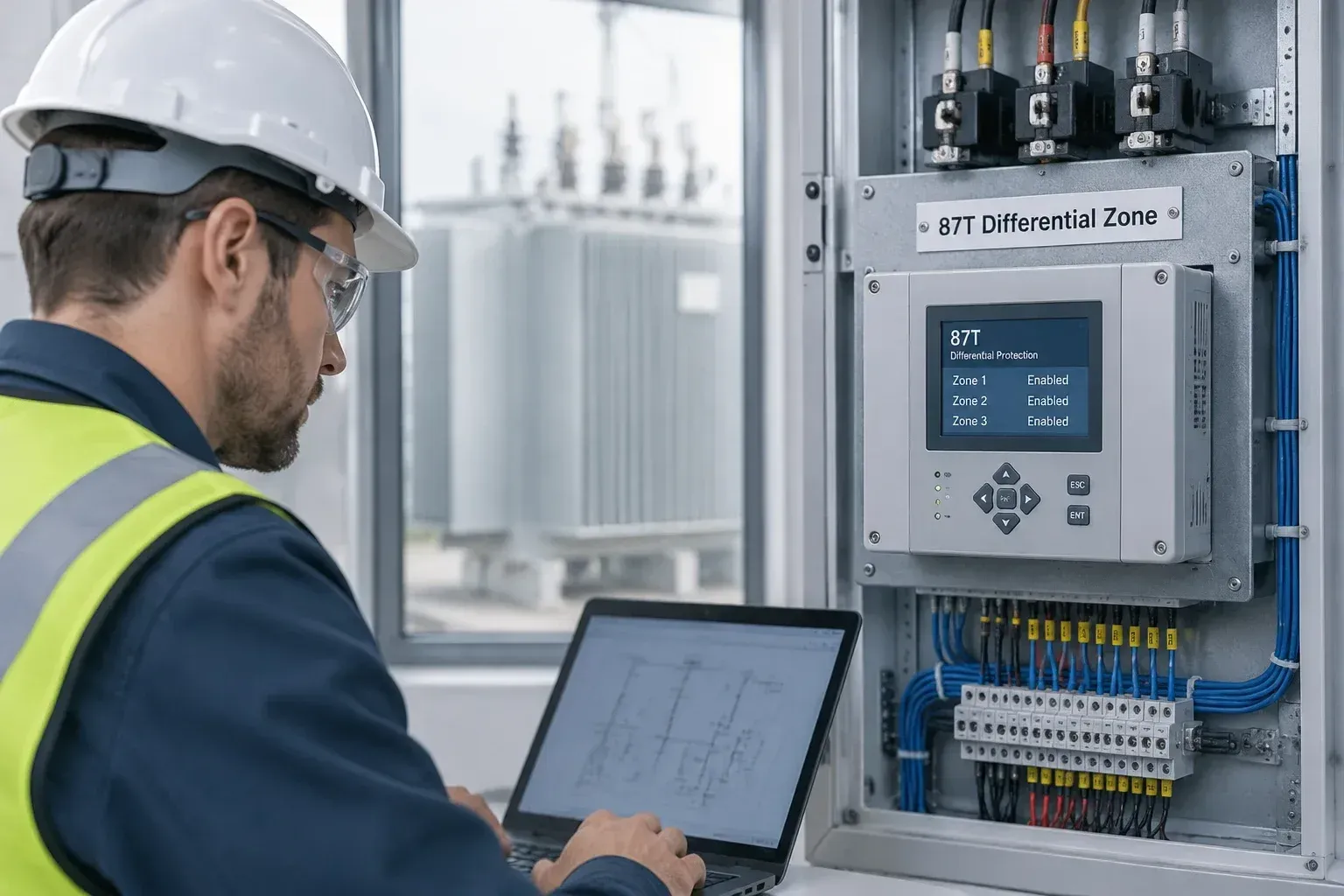
Inrush, overexcitation and CT mismatch
Most differential misoperations come from conditions that look like a fault but aren't. Energizing a transformer produces magnetizing inrush that flows on one side only, and a modern relay uses second-harmonic restraint or blocking to tell it apart from a fault. Overexcitation from high voltage or low frequency is handled by fifth-harmonic restraint. Slope settings add margin for CT error and tap-changer position.
Note: Check CT ratios, polarity and vector-group compensation before energizing. Wiring and setting errors on these points are a common reason for a trip on the first closing.
Buchholz Relay and Overcurrent Protection: What Each One Catches
A Buchholz relay watches the inside of the tank, and an overcurrent relay watches the current flowing through the terminals. They answer different questions, and neither can stand in for the other.
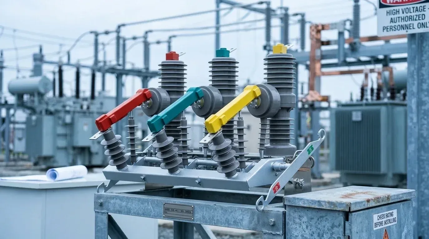
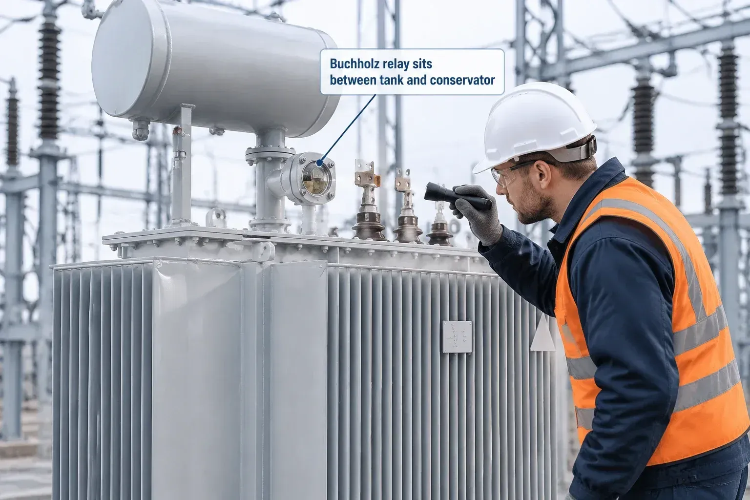
The Buchholz relay is a gas-and-oil-flow device fitted in the pipe between the main tank and the conservator of an oil-filled transformer. A slow fault such as a hot joint, a loose connection or partial core heating produces gas that rises and collects in the relay, which then trips a first-stage alarm. A severe arcing fault drives a surge of oil toward the conservator, and that flow trips the breakers directly. It catches faults that barely change the line current, which is where it earns its place next to the 87T function. The limits are plain. It only works on units with a conservator, and it says nothing about faults on the bushings or external connections.
Overcurrent protection works from the other direction. It responds to current magnitude and time, so it picks up through-faults, downstream short circuits and failed feeder protection. Used as backup, it clears what the primary protection missed or what lies outside the differential zone. It is also slower by design, because it has to coordinate with downstream devices.
In practice you fit both, because they cover different failure paths. The Buchholz relay is the one to prioritize where the main concern is a slow-developing internal fault, and overcurrent is the one you cannot drop where the transformer feeds several outgoing circuits.
What Else Protects the Tank: Pressure Relief, Sudden Pressure and Thermal Devices?
A fault arcs inside an oil-filled tank, the oil vaporizes in milliseconds, and the pressure has nowhere to go. The Buchholz relay may be too slow for that, and the differential relay trips the breaker but can't stop the pressure already building. This is where tank-mounted devices earn their place.
A pressure relief device is a spring-loaded valve that opens at a set tank pressure, vents oil, and then reseats. It limits the risk of rupture and fire, but it only acts once pressure is already high. A sudden pressure relay, sometimes called a rapid pressure rise relay, responds to the rate of pressure change instead. It usually trips the breaker faster, which is why many specifications pair it with a relief valve rather than choosing one.
Thermal devices work on a different timescale. Oil temperature indicators and winding temperature indicators watch for overload and cooling problems, typically driving alarms, fan control and, at a higher setpoint, a trip. The winding reading is normally inferred from top-oil temperature plus a current-based heating allowance, so it is an estimate, not a direct measurement.
My recommendation: treat the relief valve as the minimum on any sealed or larger oil-filled unit, add the sudden pressure relay where outage cost justifies it, and wire thermal alarms to someone who will actually respond. A trip setting nobody has tested is a guess.
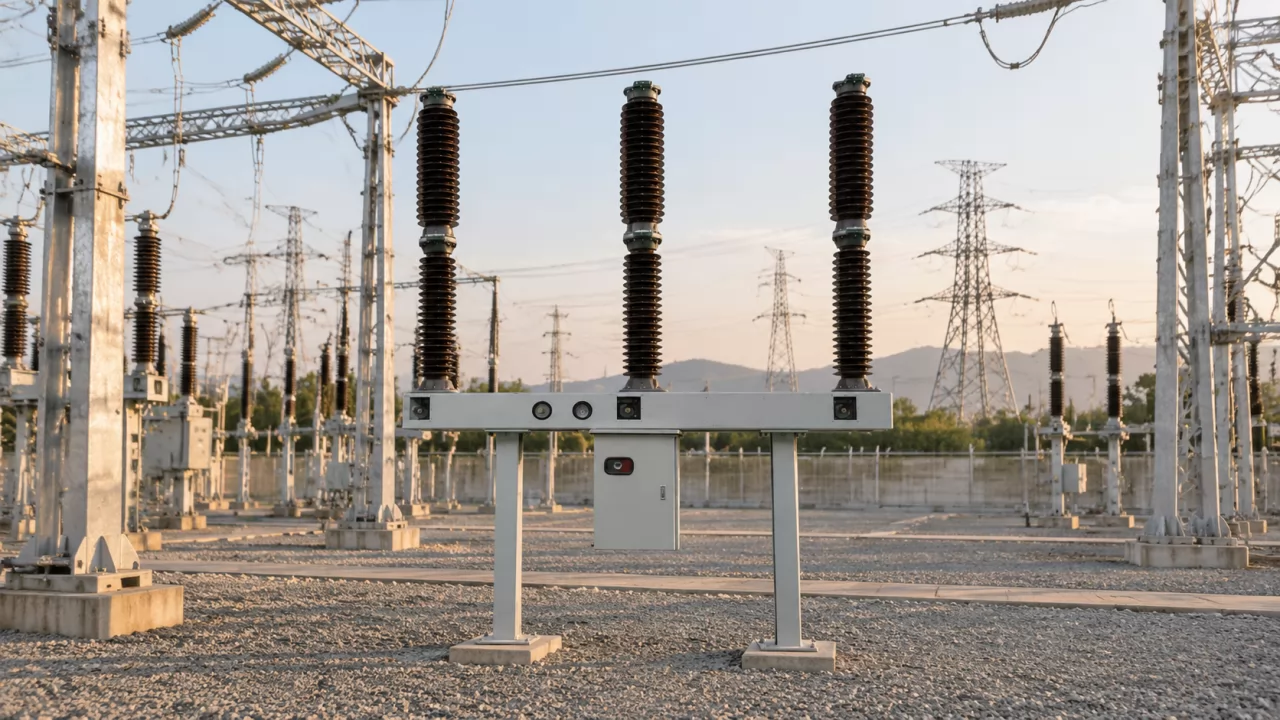
Protection for a Utility Substation Transformer
A single bank feeds a load pocket, a fault takes it out, and the relay that should have cleared it has failed along with its only DC supply. That is the scenario utility design is built to prevent. The transformer itself is rarely the weak link; the protection system around it is.
What changes at this level is redundancy. High-rated units usually get two independent relay sets, often from different manufacturers, so a firmware flaw or a settings error cannot disable both. The differential function, overcurrent backup, and tank devices are split across them, and each set is commonly tied to its own trip coil on the breaker.
Dual DC supplies follow the same logic. Two battery banks with separate chargers and separate wiring routes mean one ground fault or one failed cell string does not leave the relays blind. Supervise both, and alarm on loss of either one.
Online monitoring sits alongside, not in place of, protection. Dissolved gas sensors, bushing monitors and temperature trending give early notice of a developing problem, which matters because replacing a large unit takes a long time and costs far more than the instruments.
The trade-off is complexity. Every added relay, trip path and monitor is another thing to test, so keep the scheme as simple as the consequence of failure allows.
Protection for an Industrial Plant Transformer
A utility transformer is protected mainly to save the asset and the grid. A plant transformer is protected to keep the process running, and that shifts the priorities.
Mid-size units, often in the low-to-mid MVA range, usually still get a differential relay and a gas or pressure device if oil-filled. The difference is what sits downstream. Feeders and motor starters must clear their own faults and ride through starting currents before the transformer's overcurrent backup ever operates, so time-grading between levels matters more than relay count.
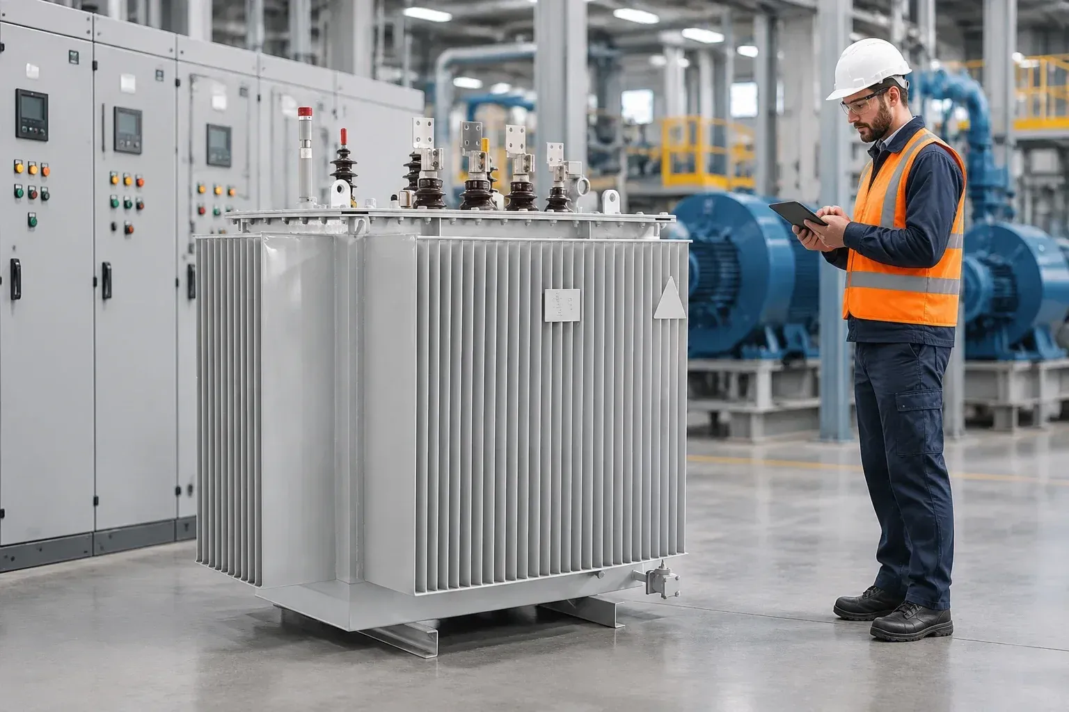
Motor starting is the usual trouble spot. A large motor drawing several times its rated current can pull the overcurrent pickup into the wrong region, and a setting that looks tidy on paper may trip the main incomer during a routine start. Run a coordination study with real motor starting data before you finalize settings.
Where Weisho Electric equipment is part of the plant's switchgear or control layout, confirm the relay trip contacts and breaker wiring match the scheme you studied.
Spend the extra effort on coordination, not on stacking more devices.
Protection for Distribution and Small Transformers
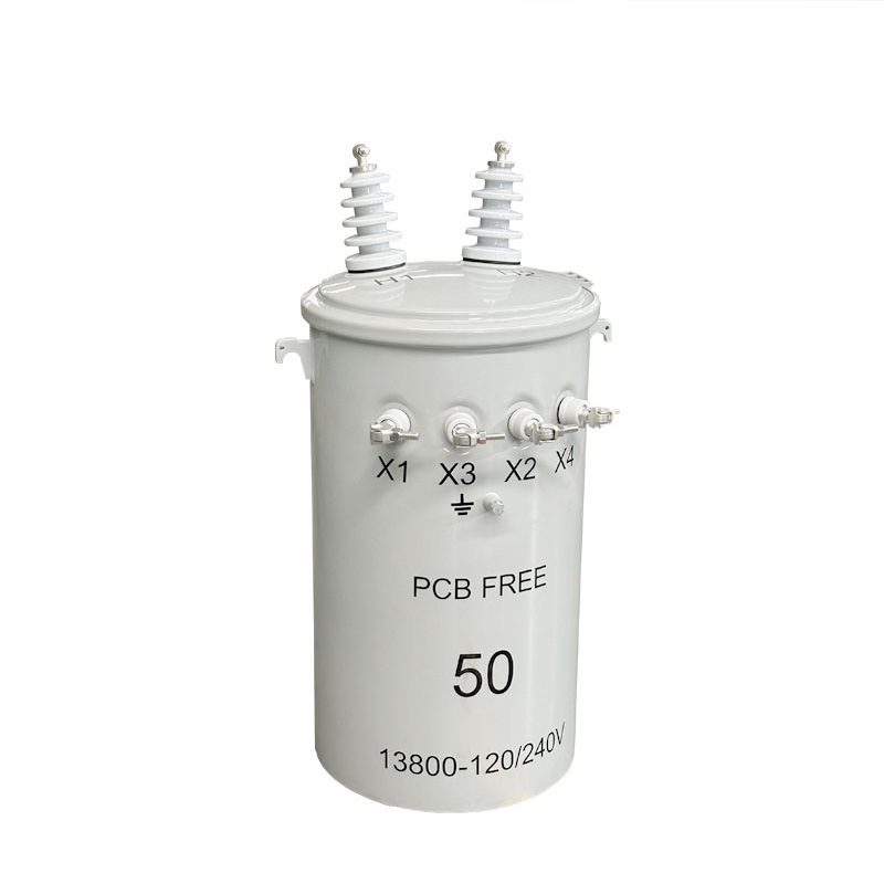
Two approaches dominate small units: a fuse on the primary side, or a circuit breaker or recloser driven by an overcurrent relay. Fuses cost little, need no auxiliary supply and have no settings to get wrong. A relay-and-breaker scheme costs more but gives adjustable curves, ground-fault sensing and a resettable trip.
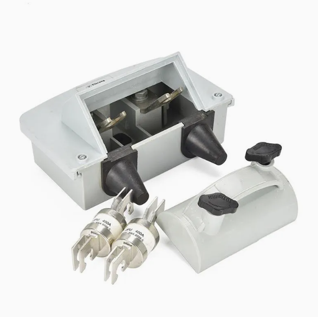
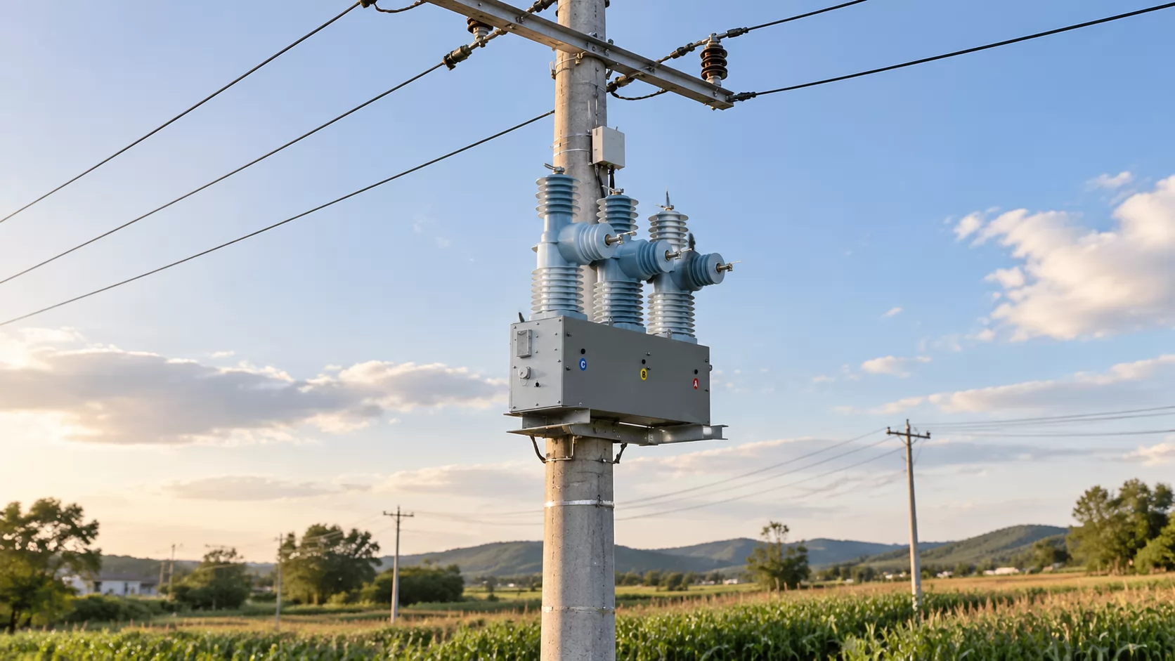
For pole-mounted and pad-mounted units where an outage affects a handful of customers, a properly sized fuse is usually the sensible answer. Size it to ride through inrush and cold-load pickup, yet clear before the transformer's thermal damage limit. Fuses struggle with low-level secondary faults and cannot tell you why they blew.
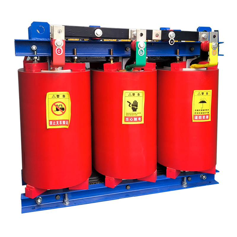
Once a unit feeds a commercial building or a critical process, step up to a breaker with overcurrent and earth-fault elements. Weisho Electric supplies transformers in this class, and the same logic applies to any make: spend on protection in proportion to what the outage costs, not to the nameplate alone. Differential protection rarely pays at this size.
How Do Dissolved Gas Analysis and Condition Monitoring Fit In?
A relay only acts once a fault is already happening. So where does the slow stuff get caught, like a hot joint, partial discharge or overheated paper? That is the job of dissolved gas analysis (DGA), a laboratory or online test that measures gases dissolved in the mineral insulating oil. Hydrogen, acetylene, ethylene and carbon monoxide each point to a different kind of stress, and a rising trend can show a problem developing months before any relay sees it.
DGA complements protection and does not replace it. A relay clears a fault in milliseconds; DGA tells you whether one is forming. Neither covers the other's gap.
Two practical points. Trend matters more than a single sample, so keep a consistent sampling interval and lab. And online gas monitors suit critical units where a failure is costly, while periodic oil sampling is usually enough for mid-size ones. Interpretation commonly follows IEC 60599 or IEEE C57.104, and an unexplained jump should prompt a resample before anyone de-energizes.
Which Standards Govern Transformer Protection?
Rule of thumb: design the transformer to IEC 60076, apply the relays by IEEE C37.91, and let the local grid code overrule both where it is stricter. IEC 60076 is the international series for power transformers, covering ratings, temperature rise, testing and short-circuit withstand. IEEE C37.91 is the guide for applying protective relays to power transformers.
The split holds because the two documents answer different questions. One defines what the transformer must survive, the other how to detect and clear what it cannot. It breaks at the utility boundary. Grid codes and utility specifications often dictate relay redundancy, clearing times and settings review, and those requirements vary by country and operator. Check them before finalizing a scheme.
Short glossary
87T — the ANSI device number for transformer differential protection.
Restraint — a relay feature that raises the trip threshold or blocks tripping during conditions such as inrush or CT error.
Inrush — the large, harmonic-rich current drawn briefly when a transformer is energized.
Through-fault — a short circuit outside the transformer that still sends heavy current through its windings.
Buchholz gas — gas released by oil decomposition during an internal fault, collected in the Buchholz relay.
How Do You Choose the Right Protection Scheme for Your Transformer?
Work through five decisions in order, because each one narrows the next.
Fix the rating and construction. Above small distribution size, plan on 87T differential plus overcurrent backup; oil-filled units add a gas or pressure device.
Price the consequence of failure. A single-feed unit with no spare justifies redundant relays and dual DC supplies. A unit with a ready replacement may not.
Check the location. Utility interconnection points bring grid code requirements on clearing times and redundancy that override your preferences.
Be honest about maintenance capacity. A scheme nobody can test or interpret is worse than a simpler one that gets tested, so match complexity to your crew.
Verify before energizing. Review relay settings, CT ratios and polarity, and coordination with upstream and downstream devices, then run secondary injection tests and trip checks.
Skipping step five is the common failure. Many misoperations trace to wiring and settings errors found only on the first energization, not to a poor choice of relay. If you are buying switchgear or transformer-side equipment from a supplier such as Weisho Electric, ask for the data your settings study needs, including impedance and CT details, before the order is placed.
FAQ
Is differential protection always required?
No. Small distribution units usually rely on fuses or overcurrent relays, while larger or critical units normally get 87T.
Can a Buchholz relay replace differential protection?
No. It sees only gas and oil movement inside the tank, not winding or terminal faults.
How often should relays be tested?
Follow your utility or site maintenance policy; intervals typically run from one to several years, and always after setting changes.
What causes false trips on energization?
Inrush current is the usual cause, along with CT polarity or ratio errors and wrong restraint settings.
Does dry-type protection differ from oil-filled?
Yes. Dry-type units have no gas or pressure devices, so they depend on electrical relays and winding temperature monitoring.
Before commissioning, check CT polarity and settings against the manufacturer's impedance data.
Effective transformer protection is layered: electrical relays such as differential and overcurrent catch winding and terminal faults, while Buchholz, pressure, and thermal devices guard the tank. Match the scheme to the transformer's size and criticality, and confirm it with proper testing before energizing. For your next step, gather the nameplate impedance, CT data, and upstream coordination settings, then have a qualified protection engineer review them before commissioning.