I. Introduction:
What Exactly is a High Rupturing Capacity (HRC) Fuse?
The High Rupturing Capacity (HRC) fuse stands as a cornerstone of modern electrical safety architecture. This indispensable safety device is meticulously engineered to interrupt, with absolute certainty, extremely high fault currents.
These currents often soar past the 80 kA threshold whenever a circuit encounters a severe overload or a catastrophic short-circuit event. Its primary purpose is to act as the circuit's last line of defense, safeguarding prohibitively expensive equipment from terminal damage.
The HRC fuse also actively works to prevent the ignition of fire hazards within critical infrastructure. The mechanism behind its impressive capability involves a precisely designed fusible element housed within a body tightly packed with high-purity quartz sand. This sand serves as the essential arc-quenching medium.
This internal configuration ensures that even under the most violent fault conditions, the current is swiftly, predictably, and reliably quenched, safely isolating the faulty section of the power system. It is this combination of rapid response and extreme fault clearance that elevates the HRC fuse above standard protection devices.
Historical Context and Critical Role in Modern Power Distribution
The dawn of industrial electrification relied heavily on rudimentary circuit protection methods, such as simple rewirable fuses or early, unsophisticated air circuit breakers. As power grids expanded and industrial loads intensified, the short-circuit potential of the network surged dramatically.
This surge frequently exceeded the tens of thousands of amperes mark. Traditional, low-breaking-capacity fuses proved terrifyingly inadequate for these "high-energy faults," often failing catastrophically by exploding or ejecting plasma. They thus exacerbated the initial accident instead of mitigating it.
The High Rupturing Capacity fuse was conceived specifically to address this dangerous gap in high-energy fault protection technology. It features a robust, fully enclosed structure paired with highly efficient arc suppression techniques. This allows it to safely absorb and extinguish the immense energy unleashed during a momentary short circuit.
Today, the HRC fuse is a mandatory component in modern substations, heavy industrial facilities, and large commercial developments. It protects main incoming lines and vital circuits to ensure system reliability, equipment integrity, and the fundamental safety of personnel.
Key Takeaways (Core Engineering Insights)
Primary Function: HRC fuses are designed to safely interrupt extremely high fault currents (the 'High Rupturing Capacity' feature).
Structural Secrets: The core construction relies on a high-strength ceramic body and tightly packed high-purity silica sand for superior arc quenching.
Engineering Advantage: They possess a unique Current Limiting Characteristic, cutting off the current before it ever reaches its theoretical peak, which is crucial for protecting sensitive downstream components.
Selection Essentials: Proper specification mandates careful consideration of the rated current, rated voltage, breaking capacity, and accurate Time-Current curve coordination (selectivity).
Maintenance Protocol: Following a fault, the entire fuse unit must be replaced, and the replacement must be of the exact identical specification and model.
II. Dissecting the HRC Fuse: Structure and Operation
The remarkable ability of the HRC fuse to safely manage and interrupt dangerously high energy levels is a direct result of the perfect synergy. This synergy exists between its ingenious structural design and the fundamental principles of physics and chemistry employed within.
Deep Dive into the HRC Fuse's Core Components
The exceptional performance under duress is attributable to 3 highly specialized components working in concert. Each component is engineered to withstand the extreme violence of a major fault event.
1. The Fusible Element (The Trigger)
The elements are almost exclusively manufactured from pure silver or silver-plated copper. Silver offers extremely low resistivity (low steady-state resistance) and its vapor, produced upon melting, has minimal adverse effects on surrounding insulation. This ensures the fuse does not contribute unnecessary heat during normal operation.
Far from being a simple, uniform wire, the fusible element incorporates precisely engineered narrow points, known as "Necks" or "Waists," strategically placed along its length. These constricted areas guarantee that when the fault current surges, the heat (Joule heating) concentrates exactly at these predetermined points, ensuring the element melts quickly and exactly where it should. Multiple necks are often utilized in series to facilitate the rapid segmentation and cooling of the resulting electric arc.
Some fuse designs integrate specialized low-melting-point solder spots (often tin) at strategic points along the silver element, a feature sometimes referred to as the "M-Effect." During minor overcurrent conditions, these low-temperature solder spots melt first, causing the surrounding silver to alloy rapidly and melt faster than pure silver alone would. This crucial detail significantly improves the fuse's response time and sensitivity to minor, sustained overloads.
2. The Robust Body (The Containment Vessel)
The fuse body is typically constructed from high-strength ceramic (such as steatite) or specialized, heat-resistant synthetic compounds. These materials must exhibit exceptional mechanical strength, superior thermal endurance, and outstanding insulation properties.
The body's function is to be robust enough to withstand the immense heat, internal pressure, and shockwaves generated inside the fuse during the high-current interruption process. It acts as a sealed containment vessel, absolutely preventing any leakage or explosive rupture of the internal arc-quenching media and the electrical arc itself.
3. The Arc-Quenching Filler (The Extinguishing Agent)
The interior of the fuse is densely packed with specially screened, treated, and high-purity Silica Sand (crystalline silicon dioxide). It is imperative that this quartz sand is perfectly dry and possesses a specific, tightly controlled particle size distribution to ensure maximum efficiency.
The quartz sand filler is arguably the HRC fuse's most critical component, delivering 3 essential functions simultaneously. These functions include Heat Dissipation (due to high specific heat capacity), Cooling (as it vaporizes upon contact with the arc, carrying heat away), and, most critically, Vitrification.

The HRC Fuse's "Hyper-Speed" Arc Extinction Mechanism
The complete interruption sequence within an HRC fuse is a complex, instantaneous interplay of physical and chemical phenomena. This process is typically executed at breathtaking speed, often concluding in 0.005 to 0.02 seconds, which is significantly faster than any mechanical circuit breaker.
The short-circuit current surges, causing the narrow neck sections to heat rapidly due to Joule heating (P = I²R). This forces the silver element to vaporize and melt within milliseconds, creating the initial breach. As the molten element separates, a high-temperature, high-pressure electric arc immediately strikes across the break, attempting to maintain the current flow. This arc is the source of massive energy release.
The intense heat of the arc instantaneously melts the surrounding, densely packed quartz sand. The molten silica then rapidly cools the arc while simultaneously wrapping around it, forming a solidified, non-conductive glass-like substance (Vitrification).
This glass-like barrier not only absorbs the arc energy but also immediately fractures and extinguishes the conductive plasma channel. It does this by rapidly lengthening and splitting the arc root. With the conductive path completely and permanently blocked by the vitrified silica, the current is rapidly choked off and forced to zero, safely isolating the faulted circuit section.
Crucial Engineering Insight: The phenomenon of quartz sand "vitrification" is the central principle enabling the HRC fuse's supreme efficiency in arc quenching. It represents a permanent, irreversible transformation that converts the arc's high thermal energy into a chemical and physical blockage, a capability far exceeding that of traditional air-break or magnetic-blowout devices.
[Video Resource: HRC Fuse 3D Structure and Arc Quenching Animation]
(View a 3D animated demonstration illustrating the internal melting, arc formation, and subsequent quartz sand quenching action of an HRC fuse.)
III. Core Characteristics and Engineering Comparison
The true value proposition of the HRC fuse is demonstrated through its superior performance metrics. This is especially true when benchmarked against traditional low-breaking-capacity fuses or even standard industrial circuit breakers.
Comparative Analysis: HRC Fuse vs. Common Alternatives
| Characteristic | HRC Fuse (High Rupturing Capacity) | Low-Breaking-Capacity Fuse (e.g., Rewirable) | Miniature Circuit Breaker (MCB) |
| Breaking Capacity | Extremely High (Typically ≥ 40 kA, often up to 80 kA or higher) | Low (Typically ≤ 4 kA) | Moderate (Commonly 6 kA or 10 kA) |
| Arc Quenching Medium | High-Purity Silica Sand (Highly efficient, sealed) | Air (or no specialized medium) | Air (utilizes arc chutes and magnetic blowout) |
| Current Limiting Ability | Extremely Strong (Interrupts current within the first half-cycle) | None | Weak or Moderate |
| Post-Operation State | Must be replaced entirely | Fusible wire can be replaced, or the unit replaced | Can be reset and reclosed |
| Applicable Use | Industrial main incomers, substations, and high-capacity switchgear | Residential homes, low-power auxiliary circuits | Residential, commercial branch circuits |
| Reliability/Stability | Extremely high, non-deteriorating characteristics | Low (Susceptible to environmental effects, manual wire replacement error) | Good |
Further Performance Advantages of HRC Fuses
The HRC fuse possesses a key Non-Deterioration Property. Unlike mechanical protection devices or older fuse technologies, the protection characteristics of an HRC fuse remain absolutely stable over time. This stability is a key differentiator, ensuring that the fuse's performance parameters do not drift or degrade over decades of inactivity.
They also have an Ultra-Fast Clearance Speed. HRC fuses can accomplish the total current interruption in an incredibly short duration, typically completing the isolation well within the first alternating current half-cycle. This remarkable speed is not merely an advantage; it is an absolute necessity for protecting fast-acting, expensive solid-state electronic equipment.
Safety Mandate: Under no circumstances should a low-breaking-capacity fuse or standard circuit breaker be substituted for an HRC fuse in an application where high fault currents are present. Such a mistake is highly likely to result in component destruction and a severe safety catastrophe.
IV. The Unique Current-Limiting Characteristic (The Defining Feature)
This specific attribute represents the most compelling engineering rationale for selecting an HRC fuse. It fundamentally separates its protective principle from that of even high-rating mechanical circuit breakers.
Defining Current Limiting: Cut-off vs. Prospective Current
In the theoretical event of an unprotected short circuit, the fault current would rise rapidly, dictated only by the system's short-circuit impedance, until it reached a massive Prospective Peak Current. This theoretical peak can easily be hundreds of thousands of amperes.
Even the fractional-second rise to this point subjects cables, busbars, switchgear, and downstream equipment to immense, destructive electrodynamic forces and intolerable thermal stresses. The unique Current Limiting Characteristic of the HRC fuse is defined by its ability to utilize its hyper-speed arc quenching mechanism to interrupt the fault current before it has even reached this theoretical Prospective Peak. It cuts the fault in the very early stages of the current rise.
Prospective Peak Current: The maximum current peak theoretically reachable without any protective device intervention.
Actual Cut-off Current: The maximum current peak that the HRC fuse actually allows the fault to reach before it forces the current to zero.
Because the Actual Cut-off Current is drastically lower than the Prospective Peak Current, the HRC fuse effectively and immensely reduces the destructive potential of the fault event. This proactive protective action is professionally termed "Current Limitation."

Dynamic Behavior: Interpreting the Time-Current (T-C) Curve
The Time-Current (T-C) Characteristic Curve is the essential engineering tool—the "road map"—that guides protection selection and coordination across a distribution network. This curve precisely plots the time required for a fuse to operate (melt) at various fault current magnitudes.
For HRC fuses, the T-C curve highlights 2 critical performance aspects.
Predictability and Precision: The curve is typically very steep and highly defined, guaranteeing a consistent, reliable, and predictable response when a fault occurs. This makes system protection design much more robust.
Selective Coordination (Discrimination): In complex power systems, the goal is always to achieve perfect selectivity. This means that if a fault occurs on the most downstream branch, only the protective device immediately upstream of the fault should operate, allowing the rest of the main system to remain energized. The fundamental engineering principle to achieve this is that the T-C curve of the downstream protective device must consistently lie below the T-C curve of the upstream device.
Engineers must precisely compare and match the T-C curves of all fuses and circuit breakers to ensure flawless protection selectivity across all fault current levels.
Design Pointer: When engineering critical electrical systems, the current-limiting property achieves much more than just protecting the cable insulation and busbars. Critically, it allows lower-rated downstream switchgear (such as contactors or small circuit breakers) to survive a major short-circuit fault. This is because the HRC fuse restricts the total fault energy to a level well within their tested short-time withstand rating.
V. Major HRC Fuse Classifications and Application Areas
HRC fuses are systematically categorized based on rigorous international standards, design form factor, and their specific intended use. This ensures engineers can select the perfect protective profile for any load.
Common HRC Fuse Types and Their Protection Profiles
The International Electrotechnical Commission (IEC 60269) standard categorizes fuses based on their application and functionality. This classification is the key reference for any electrical engineer:
gG / gL Type (General Purpose):
Primary Application: These are the most common, general-purpose fuses.
Characteristic: They provide full-range protection, meaning they offer protection against both overload currents (low multiples of the rated current) and short-circuit currents (high multiples of the rated current). They are suitable for the general protection of cables, distribution boards, and busbar systems.
aM Type (Motor Protection):
Primary Application: Specifically designed for protection within motor circuits.
Characteristic: They only provide short-circuit protection. The design is intentionally "slow" enough to withstand the high, momentary inrush current generated when a motor starts (which can be 6x to 8x the rated current) without blowing. For continuous, normal overload protection, an aM-type fuse must be paired with a separate overload device, such as a thermal relay.
gR / aR Type (Semiconductor Protection):
Primary Application: Used to protect extremely sensitive and expensive solid-state semiconductor components, including thyristors, power diodes, and IGBT modules.
Characteristic: These are classified as Ultra-Fast Acting Fuses. They exhibit an extremely high speed of operation and the strongest current-limiting capability because semiconductor devices have virtually no tolerance for momentary thermal energy.
NH / DIN Type: These are common European standard blade-contact fuses, heavily used in industrial switchgear and distribution cabinets.
Cylindrical / Cartridge Type: These are smaller, cylindrical fuses often used for panel mounting and protection within equipment enclosures.
Typical Application Environments
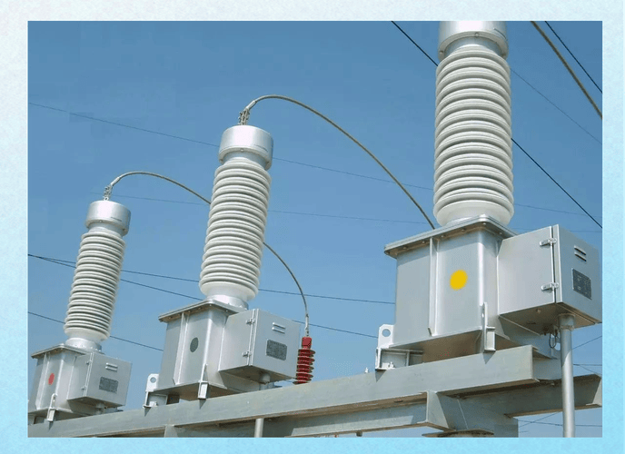
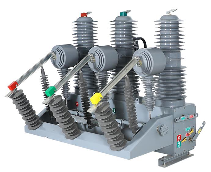
Industrial and Commercial Main Switchboards: HRC fuses are invariably installed at the point of origin, such as the main incoming line, the secondary side of a power transformer, or at the start of high-capacity feeder lines.
Transformer and Capacitor Bank Protection: HRC fuses effectively guard against short-circuits on the primary side of transformers or inrush current faults in capacitor banks.
Short-Circuit Protection for Motors: Used in combination with contactors and thermal overloads (utilizing the aM type).
High-Specification Test Instruments: In the high-ampere range of professional multimeters, the HRC fuse is the only acceptable protective choice. This prevents catastrophic instrument failure or explosion during accidental high-current measurement.
UPS / Inverter Systems: Employed to protect the highly sensitive and expensive power electronic modules within uninterruptible power supplies.
VI. Engineer Selection, Regulatory Standards, and Best Practices
Selecting and deploying an HRC fuse is a critical, rigorous engineering task. It must adhere strictly to international standards and the detailed requirements of the system design.
Essential Considerations for Engineer Selection
The engineer must comprehensively evaluate and specify the fuse based on the following 5 core parameters to ensure complete system protection:
Rated Current: This is the current value the fuse can safely carry for a prolonged period without deteriorating. It must be greater than or equal to the normal, full-load operating current of the circuit it protects.
Rated Voltage: This is the voltage the fuse can reliably withstand after it has melted and interrupted the current. It must be greater than or equal to the nominal system voltage.
Breaking Capacity: This is the absolute maximum short-circuit current the fuse is capable of safely interrupting. This is the single most critical parameter; it must be greater than or equal to the Maximum Prospective Short-Circuit Current calculated for the exact point of installation.
Utilization Category: The engineer must select the category (e.g., gG, aM) based on the specific load type. This ensures the fuse's inherent protective characteristics perfectly align with the operational needs of the connected equipment.
T-C Curve Coordination: This involves meticulous comparison of the time-current curves between upstream and downstream protective devices. The goal is to ensure the curves never intersect, thereby guaranteeing perfect selective protection across the entire range of potential fault levels.
International Standards and Compliance
The design, testing, and performance validation of HRC fuses are governed primarily by the comprehensive IEC 60269 series of standards. These standards meticulously define the physical dimensions, electrical characteristics, mandatory test procedures, and classification system, which ensures product reliability and interchangeability across different manufacturers.
In North American markets, the corresponding safety criteria are typically referenced in the UL standards. Strict adherence to these published standards is the absolute foundation for ensuring system compliance and safety.
Maintenance and Replacement Protocols
The maintenance protocol for HRC fuses is exceptionally simple but unequivocally strict:
Single-Use Protective Device: Once an HRC fuse has operated (melted), its internal structure—the silver element is gone, and the quartz sand has vitrified—has undergone an irreversible physical and chemical change. The entire fuse unit must be replaced in its entirety; there must be no attempt whatsoever to repair it or to re-wire the element.
Exact Specification Match is Mandatory: The replacement fuse must be of the exact same brand, model, Rated Current, Rated Voltage, and Breaking Capacity as the original unit. Utilizing a fuse of incorrect specification, particularly one with an insufficient breaking capacity, poses a severe risk of catastrophic failure during the next short-circuit event.
De-energized Operation Only: The replacement of the fuse unit must always be conducted under fully de-energized conditions, requiring the upstream power source to be safely locked out and tagged out.
Operational Note: HRC fuses typically incorporate a visual indicator or a striker pin that is ejected upon melting. This feature facilitates rapid identification of the operated fuse by maintenance personnel. Before replacement, the underlying root cause of the fault must be conclusively identified and remedied.
VII. Conclusion
Summary of the HRC Fuse's Core Value
The HRC fuse holds an unshakeable position in modern electrical safety due to its unparalleled combination of extreme breaking capacity, hyper-fast clearance speed, and defining current-limiting ability. It performs two essential functions: it isolates the faulted circuit instantaneously, and, critically, it limits the peak magnitude of the fault current.
By doing so, it minimizes the collateral damage to the entire distribution system, especially protecting sensitive downstream equipment from irreparable harm. HRC fuses are, therefore, the foundational elements upon which the safety and reliability of high-power electrical systems are built.
Final Outlook: The Unwavering Guardian of Power Systems
Even with the continuous advancement of intelligent electronic protection technologies and sophisticated smart circuit breakers, the inherent advantages of the HRC fuse remain unmatched. Specifically, these include its immutable current-limiting physics, cost-effectiveness, and extremely high passive reliability (zero moving mechanical parts).
They will continue to serve as the most dependable and fastest-acting passive protective devices in all critical power systems, particularly those safeguarding semiconductors and high-energy utility grids. This ensures the sustained safety of electrical consumption for decades to come.

Frequently Asked Questions (FAQ)
Q1: Both HRC Fuses and standard Miniature Circuit Breakers (MCBs) interrupt fault currents. Why is the HRC mandatory in high-power industrial settings?
A: The core differentiation lies in Breaking Capacity and Current Limitation. Most common MCBs are rated for a breaking capacity of 6 kA or 10 kA, whereas HRC fuses are designed for 80 kA to 120 kA. In industrial or substation environments, the actual potential short-circuit current vastly exceeds the safe limits of an MCB.
Furthermore, the HRC fuse is a current-limiting device, cutting off the current before its peak. The MCB is generally a non-limiting or poorly limiting device, meaning the full peak energy is released before it manages to trip, causing significantly more damage downstream.
Q2: What are the main protection differences between a fuse and a circuit breaker?
A: A fuse is a single-use protective element whose main strength is its high-speed, reliable, and precise short-circuit protection, coupled with its superior current-limiting capability. A circuit breaker (like an MCB or ACB) is a reusable mechanical device whose strengths include flexible trip-setting adjustments, convenient overload protection, and operational ease.
In critical, high-energy circuits, they are often used synergistically. The fuse provides ultra-fast short-circuit and limiting protection, while the breaker handles the flexible overload settings and provides the necessary operational isolation.
Q3: What is the I-squared-t value of a fuse, and what is its engineering significance?
A: The I-squared-t (Amperes-Squared Seconds) value represents the time integral of the Joule heat energy generated as current flows through the fuse. This makes it the key metric for measuring the fuse's melting characteristic.
In engineering practice, it serves 2 purposes. 1. Protection Selectivity: This ensures there is a substantial margin between the I-squared-t values of upstream and downstream fuses to guarantee only the desired fuse operates during a fault. 2. Equipment Matching: The total I-squared-t passed by the operating fuse must be less than the maximum I-squared-t withstand rating of the protected cable or device. This confirms the component will not be damaged before the fuse has a chance to clear the fault.
Q4: If an HRC fuse repeatedly blows, what is the required course of action?
A: An HRC fuse operation is never incidental; it indicates a severe and persistent fault within the circuit. Step 1: You must absolutely not replace the fuse immediately and re-energize the circuit.
Step 2: A full fault investigation must be conducted using specialized instruments (such as insulation testers and multimeters) to identify and locate the root cause (e.g., dead short, ground fault, severe motor lock-up).
Step 3: Only after the fault has been definitively confirmed and rectified can a new HRC fuse of the exact matching specification be installed and the circuit re-energized.
Q5: What is the practical difference in application between the gG and aM HRC fuse types?
A: The distinction is crucial. gG Type (General Protection): Used for protecting static loads or loads not sensitive to high inrush currents. It provides both overload protection (for currents slightly above the rating) and short-circuit protection. It is suitable for protecting general cables, heaters, and ordinary distribution boards.
aM Type (Motor Protection): Exclusively for short-circuit protection. The aM fuse is intentionally designed to be "slow" to tolerate the immense, normal inrush current of a starting motor. Consequently, an aM fuse must be supplemented with an overload protection device (like a thermal relay or motor protection circuit breaker) to handle prolonged, low-level overcurrents.
Q6: What is the practical significance of the HRC fuse's "non-deterioration" property in maintenance?
A: The "non-deterioration" property means the fuse's operating characteristics (such as its melting time and current-limiting value) do not degrade or change over time, even under years of normal operating temperature and ambient conditions. The practical significance for maintenance is twofold.
1. High Reliability: Engineers can trust that a fuse installed 10 years ago will perform precisely according to its original published specifications. 2. No Preventive Replacement: As long as it hasn't operated, an HRC fuse requires no scheduled preventive replacement, unlike some mechanical switches or thermal devices. This significantly reduces maintenance costs and system downtime risks.
Q7: What must be done if the grid's short-circuit current exceeds the HRC fuse's breaking capacity?
A: If the installation point's Maximum Prospective Short-Circuit Current exceeds the fuse's Rated Breaking Capacity, the fuse is guaranteed to fail catastrophically and explode during a major fault, unable to safely clear the current. Solution: It is mandatory to install an upstream protective device (such as a current-limiting reactor or a circuit breaker with a higher breaking capacity or strong limiting characteristic) to limit the actual fault current flowing through the HRC fuse to a value well below its rated breaking capacity. This is a non-negotiable safety requirement in electrical system design.