Everything You Need to Know About Grounding a Transformer Safely and Effectively
Proper electrical grounding is one of the most critical safety measures in any power distribution system. Whether you're installing a new unit for a residential solar array or maintaining industrial equipment, understanding how to ground a transformer correctly can prevent catastrophic failures, equipment damage, and even loss of life. This guide draws on over a decade of field experience to walk you through the process clearly and thoroughly.
Why Proper Earthing Matters for Power Equipment
Electrical Transformers convert voltage levels to distribute electricity safely across distances. Without adequate earthing, fault currents have no controlled path to dissipate, creating dangerous voltage potentials on equipment casings, fences, and nearby conductive surfaces. According to the Electrical Safety Foundation International, contact with improperly grounded equipment accounts for hundreds of workplace injuries annually in the United States alone.
Beyond personal safety, correct grounding protects the transformer itself. Transient overvoltages from lightning strikes or switching surges can degrade insulation and shorten equipment lifespan if they cannot be safely directed into the earth. A well-designed earthing system acts as insurance for both people and infrastructure.
Types of Installations and Their Earthing Requirements
The approach to earthing depends heavily on the type of unit and its installation context. Below is a comparison of common configurations and their distinct characteristics.
| Installation Type | Typical Voltage | Earthing Method | Common Application |
|---|---|---|---|
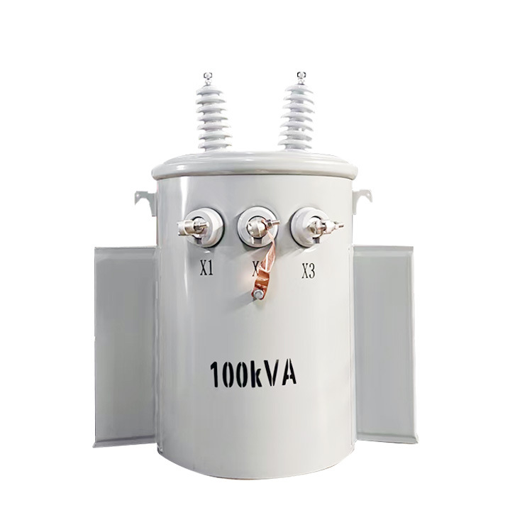
| Pad-mounted | 2.4 kV – 34.5 kV | Ground rod with mesh grid | Residential subdivisions |
| Ground-level enclosure | 4.16 kV – 69 kV | Buried ground ring with rods | Commercial and industrial |
| Pole-mounted | 2.4 kV – 34.5 kV | Down conductor to driven rod | Rural distribution |
| Substation class | 69 kV – 500 kV+ | Full ground grid with test wells | Utility substations |
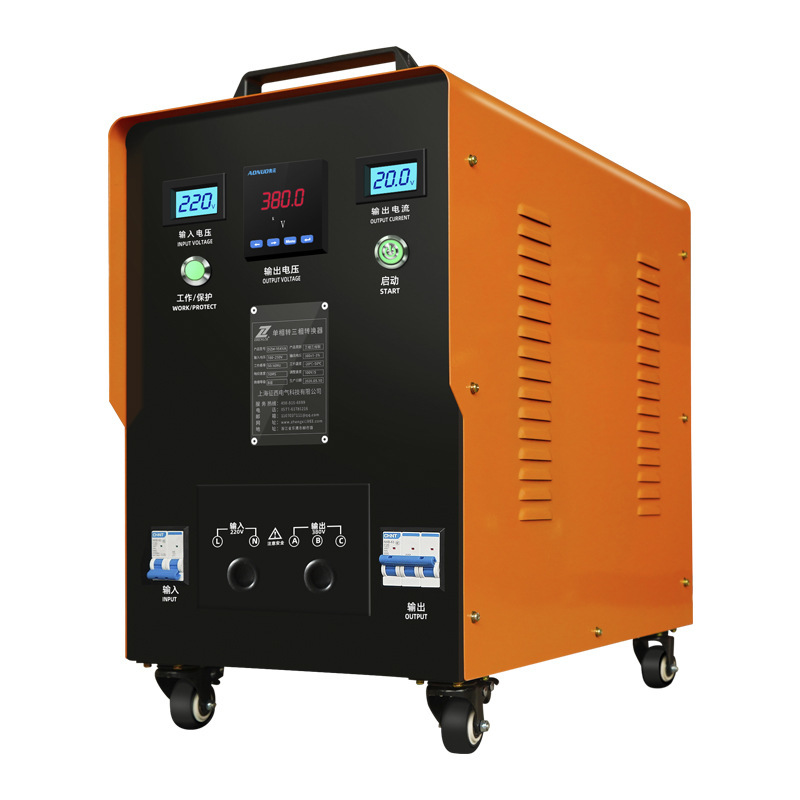
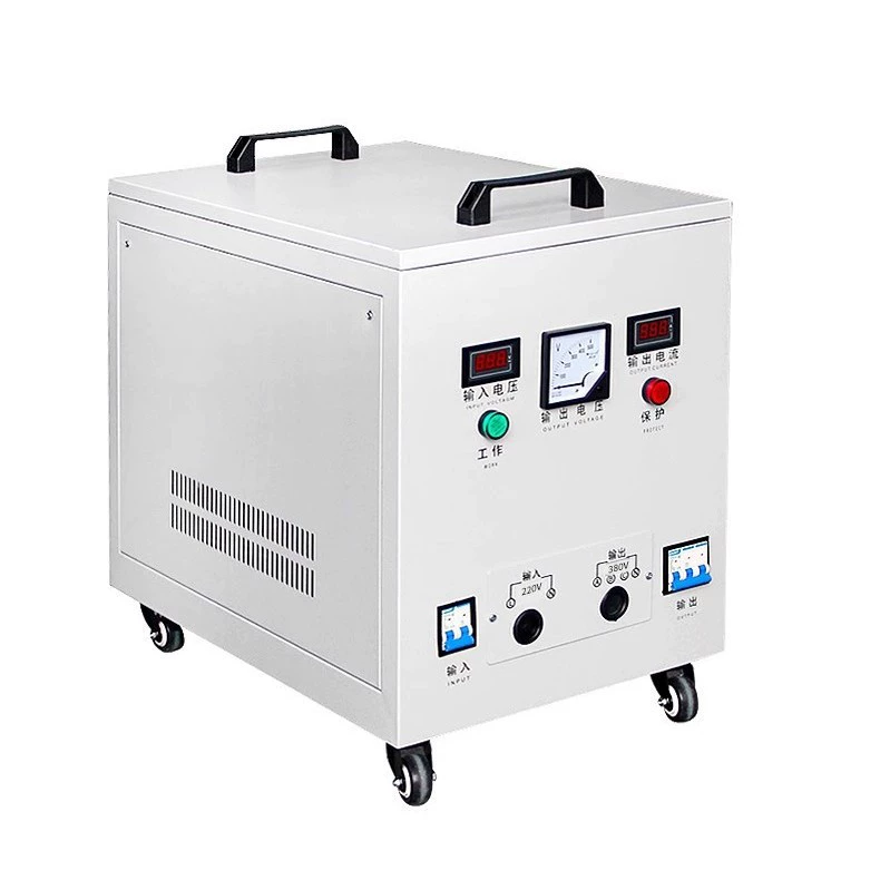
When comparing a ground transformer vs a pad-mounted transformer, the key distinction lies in accessibility and enclosure design. Pad-mounted units sit on concrete pads with tamper-resistant cabinets, while ground-level enclosed units may use walk-in housings that require more extensive earthing grids due to personnel access.
Step-by-Step Installation Process
1. Site Assessment and Soil Resistivity Testing
Before driving a single rod, measure soil resistivity using a four-point (Wenner) method. Soil composition dramatically affects how well fault currents dissipate. Sandy or rocky soils may require deeper rods, chemical treatment, or enhanced grounding electrodes to achieve acceptable resistance values.
The target resistance for most distribution-class equipment is 25 ohms or less, though many utilities specify 5 ohms or less for critical installations. Document your readings thoroughly — they form the baseline for future maintenance testing.
2. Selecting and Installing Ground Electrodes
Copper-clad steel rods (typically 5/8-inch diameter, 8–10 feet long) remain the industry standard. Drive them vertically into undisturbed earth at least 6 feet from the equipment foundation. If a single rod cannot achieve the required resistance, install additional rods spaced at least one rod-length apart and bond them together with bare copper conductor.
For installations serving solar panel systems, the earthing system must also bond the array frame, inverter chassis, and combiner boxes into a unified grounding electrode system. This ground transformer for solar panel systems approach ensures that DC and AC fault paths are both addressed.
3. Bonding the Equipment
Connect the transformer tank, secondary neutral, surge arresters, and any metallic enclosures to the earthing electrode system using appropriately sized copper conductors. The National Electrical Code (NEC) Article 250 provides specific conductor sizing requirements based on the largest phase conductor serving the equipment.
All connections should use exothermic welds or listed compression connectors rated for direct burial. Mechanical clamps are acceptable above grade but may loosen over time in vibration-prone environments.
4. Verifying the Installation
After completing all connections, perform a fall-of-potential test to verify the system meets its design resistance. This three-point measurement technique provides the most accurate reading of actual earth resistance. Record results and photograph all connections before backfilling.

Safety Requirements and Code Compliance
Adhering to ground transformer safety requirements 2026 means following the latest editions of NEC, IEEE Standard 80 (for substations), and IEEE Standard 142 (the "Green Book" for industrial systems). Local utility specifications may impose additional constraints, so always verify with the authority having jurisdiction before beginning work.
Key compliance checkpoints include:
Step and touch voltage calculations within acceptable limits
Proper separation between earthing electrodes and underground utilities
Correct conductor sizing for available fault current
Accessible test points for periodic verification
Clear labelling of all grounding conductors and connection points
Neutral Grounding Resistor Applications
In medium-voltage systems, a neutral grounding resistor limits fault current to manageable levels — typically between 200 and 400 amperes. This technique protects step-down transformer safety by reducing the thermal and mechanical stress on windings during a ground fault, while still providing enough current for protective relays to detect and clear the fault quickly.
Resistance-grounded systems have become increasingly common in industrial settings because they dramatically reduce arc-flash energy. A 2024 study by IEEE found that resistance-grounded systems reduced arc-flash incident energy by up to 98% compared to solidly grounded alternatives in certain configurations.
Maintenance Best Practices
Installation is only the beginning. Earthing systems degrade over time due to corrosion, soil settling, and physical damage. Following ground transformer maintenance best practices means establishing a periodic testing schedule.
| Maintenance Task | Frequency | Method |
|---|---|---|
| Visual inspection of above-grade connections | Annually | Physical inspection, thermal imaging |
| Ground resistance testing | Every 1–3 years | Fall-of-potential or clamp-on method |
| Continuity verification of bonding conductors | Every 1–3 years | Low-resistance ohmmeter |
| Soil resistivity re-measurement | Every 5 years | Four-point Wenner method |
| Full system audit and documentation update | Every 5 years | Comprehensive review against current codes |
Pay particular attention to connections that transition between above-grade and below-grade environments. The soil-air interface is where corrosion accelerates most aggressively. Thermal imaging during loaded conditions can reveal high-resistance connections before they fail catastrophically.
Common Mistakes to Avoid
Even experienced electricians occasionally make errors with power system earthing. Here are the most frequent issues encountered in the field:
Insufficient electrode depth: Rods that don't reach permanently moist soil layers will show wildly varying resistance seasonally.
Using dissimilar metals: Copper conductors connected to galvanised steel without proper transition fittings create galvanic corrosion cells.
Neglecting bonding: Grounding the neutral without bonding the equipment enclosure creates a dangerous shock hazard.
Relying solely on concrete-encased electrodes: While Ufer grounds are effective, they should supplement — not replace — dedicated driven electrodes for transformer installations.
Key Takeaways
Proper earthing of power distribution equipment is both a safety imperative and a code requirement. The process demands careful site assessment, quality materials, correct installation techniques, and ongoing maintenance. Whether you're working with residential-scale equipment or industrial substations, the fundamentals remain consistent: low resistance, solid bonding, and regular verification.
If you're planning an installation, consult a licensed professional engineer for site-specific design. For existing systems, schedule a ground resistance test this quarter to confirm your earthing system still meets specifications. Proactive maintenance costs a fraction of what an unplanned failure demands.

Frequently Asked Questions
What is the acceptable ground resistance value for a distribution transformer?
Most utilities and codes require 25 ohms or less for distribution equipment, with many specifying 5 ohms or less for critical installations. The exact requirement depends on your local utility specifications and the available fault current. Always verify with the authority having jurisdiction before finalising your design.
Can I use the concrete foundation as my sole grounding electrode?
Concrete-encased electrodes (Ufer grounds) are recognised by the NEC and can be highly effective, especially in high-resistivity soils. However, for transformer installations, best practice is to supplement them with dedicated driven rods or a buried ground ring. This provides redundancy and accessible test points for periodic verification.
How often should earthing systems be tested?
Industry best practice recommends testing every one to three years, depending on soil conditions and the criticality of the installation. Facilities in corrosive soils, flood-prone areas, or those serving critical loads should be tested annually. Always retest after any nearby excavation, lightning strike, or fault event.
What size grounding conductor do I need?
Conductor sizing is determined by NEC Table 250.66 based on the size of the largest ungrounded service conductor. For example, a system with 350 kcmil copper phase conductors requires a minimum 2 AWG copper grounding electrode conductor. Consult the NEC directly or engage a licensed engineer for your specific application, as undersized conductors create serious fire and shock hazards.
Do solar panel system transformers require special grounding considerations?
Yes. Photovoltaic systems introduce both DC and AC grounding requirements that must be coordinated. The equipment grounding conductor for the array, the DC system bonding, and the AC-side earthing must all connect to create a unified grounding electrode system. Additionally, ground-fault detection requirements for PV systems (per NEC 690.41) add complexity that demands careful design coordination between the inverter manufacturer's specifications and local code requirements.