Designing a truly robust electrical control panel requires adherence to a rigorous, systematic process. This journey extends from deeply understanding the core system requirements and selecting specialized components to creating precise schematics and ensuring full compliance with stringent functional safety standards.
A successful control panel is far more than just a collection of interconnected circuit diagrams. It represents the harmonious integration of industrial safety, operational efficiency, and future scalability.
An Electrical Control Panel, often referred to as a cabinet or chassis, is a rugged, enclosed structure—typically metal or industrial-grade plastic. Inside this enclosure, critical electrical components like circuit breakers, motor contactors, Programmable Logic Controllers (PLCs), Variable Frequency Drives (VFDs), and terminal blocks are integrated.
This panel acts as the "brain" and "central nervous system" of industrial machinery, receiving input signals from various sensors and human-machine interfaces (HMIs). It executes complex logical routines to drive actuators such as motors and valves, ultimately achieving the automated operation of an entire machine or process.
The quality of the control panel design directly dictates the system's reliability, safety record, and overall production output.
Drawing upon the perspective of a seasoned electrical engineer, this guide provides a methodology that is professional, secure, and highly efficient. We aim to move beyond basic component selection and simple wiring practices to delve into the key differentiating factors of modern industrial design.
This includes the precise determination of functional safety levels, the professional coordination of Short Circuit Current Rating (SCCR), the application of advanced digital engineering tools, and optimizing the panel for efficient fabrication. We will equip you with the knowledge to build intelligent control systems that meet current regulatory demands and are engineered for the future.
Key Takeaways
Systematic Design Process: Implement a structured framework that spans all phases: detailed requirement gathering, component selection, digital modeling, manufacturing, and comprehensive testing.
Safety & Compliance First: Prioritize the calculation and coordination of the Short Circuit Current Rating (SCCR) and strictly adhere to standards like UL 508A. This includes integrating functional safety requirements based on Performance Levels (PL) or Safety Integrity Levels (SIL).
Digital Transformation: Leverage professional Electrical CAD tools for efficient schematic generation. Utilize 3D layout software to perform critical thermal simulation (CFD) and collision checks, significantly boosting design accuracy.
Design for Manufacturability (DFM): Integrate fabrication-friendly features, such as push-in terminal blocks and pre-fabricated wiring bundles, to drastically reduce assembly time and minimize human error on the shop floor.

1, Planning and Advanced Requirements
The entire design endeavor starts with meticulous planning and deep requirements analysis. The initial time and effort invested in this planning phase will determine the project's ultimate success.
This effort helps to avoid expensive rework, prolonged debugging sessions, and costly delays further down the line.
Functional Requirements and Operational Needs
First and foremost, the designer must achieve a complete understanding of the controlled equipment's type, the entire process workflow, and the intended operating logic. This fundamental comprehension dictates the appropriate selection of the core controller.
This core selection involves choosing whether that is a standard Programmable Logic Controller (PLC), a complex Distributed Control System (DCS), or a specialized motion controller.
Furthermore, it is essential to accurately tabulate the total number of all digital inputs (DI), digital outputs (DO), analog inputs (AI), and analog outputs (AO) required for the system. A crucial professional practice is to mandate a contingency of at least 15% to 20% spare I/O capacity in the design.
This necessary redundancy ensures that the system can accommodate future upgrades, unforeseen operational changes, and simplified troubleshooting procedures.
Finally, the design must clearly define the Human-Machine Interface (HMI) requirements. This involves specifying the types, quantities, and logical layout of all necessary indicators, pushbuttons, and display screens needed by the operator.
Tip: Mandating I/O redundancy in the preliminary design is a critical best practice, ensuring the system remains adaptable and avoiding cost spikes later in the project lifecycle when minor changes are requested.
1.1, Environmental and Compliance Standards
The panel’s designated operating environment fundamentally determines the type of enclosure required, directly influencing its overall protection and safety ratings. In the North American market, NEMA (National Electrical Manufacturers Association) ratings define an enclosure’s ability to withstand environmental hazards, with NEMA 12 commonly used for indoor industrial applications.
Globally, the IP (Ingress Protection) rating system is applied, with IP54 being a typical minimum requirement for light industrial environments. For installations located in potentially explosive atmospheres, strict compliance with Hazardous Location (HazLoc) certifications is mandatory. This involves selecting explosion-proof control cabinets or components that comply with specific NEC Class/Division or IEC Ex Zone classifications.
Each electrical component integrated into the panel is rated for a defined operational temperature range. Therefore, during the early design phase, engineers must calculate the internal power density and accurately estimate the cabinet’s expected temperature rise.
If the projected internal temperature exceeds the safe ΔT (temperature difference) threshold relative to ambient conditions, an active cooling system must be introduced. Common solutions include forced ventilation systems with fans and filters, heat exchangers, or air conditioning units for cabinets handling substantial heat loads.
From a compliance perspective, the European market mandates the CE mark, while the North American market typically requires UL (Underwriters Laboratories) certification, particularly under the UL 508A Industrial Control Panel standard.
Within the UL 508A framework, the Short-Circuit Current Rating (SCCR) stands as one of the most critical parameters. This rating must be carefully calculated during the design phase and clearly displayed on the final control panel’s nameplate.
1.2, Power Analysis and Distribution Strategy
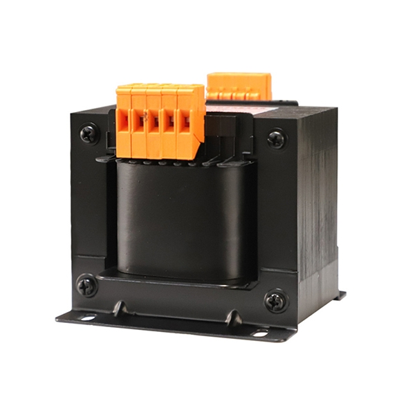
The design process must begin by clearly defining the characteristics of the incoming main power supply, including its voltage, phase configuration, and maximum load capacity. Inside the cabinet, the main power (for example, 480 V / 400 V AC) is managed and converted using specialized transformers and Switched-Mode Power Supplies (SMPS).
These devices step down the voltage to the required control power level—typically 24 V DC—and must ensure reliable electrical isolation between the power and control circuits.
A detailed calculation of the maximum running current for all system loads, including motors, heaters, and solenoids, is essential. This data is used to correctly select the size of the main breaker, all branch circuit protection devices, and the appropriate conductor gauges.
Conductor sizing must strictly follow the relevant standards (such as NEC or IEC) based on the calculated maximum current and the expected ambient temperature. This ensures that the wire will never overheat under full-load conditions.
2, Component Selection and Professional Considerations
The selection of every component is central to a successful design project. This process requires a delicate balance between achieving optimal performance, ensuring long-term reliability, managing cost constraints, and maintaining absolute regulatory compliance.
Core Components and Functional Overview
| Component Category | Typical Examples | Primary Function | Key Design Considerations |
| Control Core | PLC, DCS, Smart Relays | Executes control logic, data processing, and automation sequencing. | Processor speed, total I/O capacity, programming language flexibility, and network communication interfaces. |
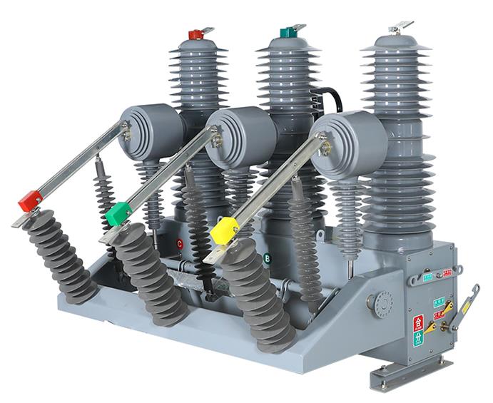
| Power & Protection | Main/Branch Circuit Breakers, Fuses, Power Supplies | Provides power conversion, isolation, and protection against overloads and short circuits. | SCCR rating, specific trip characteristics, required output power capacity, and efficiency rating. |
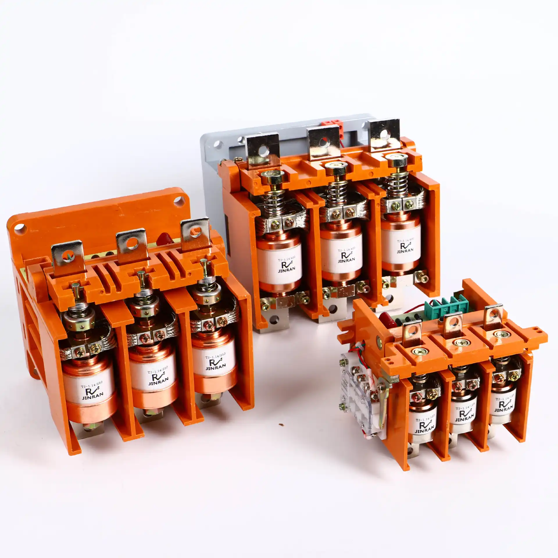
| Control & Drive | Contactors, Thermal Overloads, VFDs (Drives) | Controls the switching and protection of large current loads, especially motors. | Rated current capacity, mechanical lifecycle rating, and any requirements for external braking resistors. |
| Connection & Wiring | Terminal Blocks, DIN Rail, Wire Ducting | Ensures the safe, organized, and secure connection and termination of all wiring. | Rated current, preferred termination method, wire density, and the advantage of using push-in technology. |
| HMI & Interface | Pushbuttons, Indicator Lights, HMI Touchscreens | Provides essential operational input, visual status indication, and necessary fault diagnostic feedback. | Required environmental protection rating (IP/NEMA), visibility under ambient light, and overall operational ergonomics. |
2.1, Short Circuit Current Rating (SCCR) Calculation and Coordination
The Short Circuit Current Rating (SCCR) defines the maximum current that the control panel can safely withstand in the event of a catastrophic short circuit fault. This is not merely a suggestion but a professional and crucial compliance detail.
The overall SCCR for the entire control panel is determined by the component with the lowest short-circuit rating installed inside the enclosure. However, this rating can be strategically elevated if a current-limiting protective device is installed immediately upstream of the lower-rated component.
The designer must perform a professional protection coordination calculation to achieve this improvement. For instance, a specific contactor might only be rated for a $5 \text{kA SCCR}$.
If a highly effective current-limiting circuit breaker or fuse is installed upstream, that protective device must be capable of quickly clearing the fault current. It must restrict the actual let-through peak current to a value safely below $5 \text{kA}$.
If this coordination is proven, the contactor is deemed safe, and the overall panel SCCR can be increased. The final, calculated SCCR value must be clearly and permanently displayed on the control panel's rating plate, as this is a mandatory requirement for UL certification.
Note: SCCR coordination is the most critical element for preventing catastrophic panel failure, including fire or explosion, during an electrical fault. This complex calculation must only be entrusted to a qualified, experienced engineer.

2.2, Functional Safety Circuits and Components
Modern industrial operations demand that control systems not only execute standard functions but also possess robust, dedicated safety mechanisms. Functional safety is the engineering practice of designing systems according to rigorous standards—specifically IEC $61508$/IEC $62061$ (defining SIL, Safety Integrity Level) and ISO $13849$ (defining PL, Performance Level)—to mitigate risks arising from equipment failures.
The safety circuit design must be directly guided by the results of the comprehensive Risk Assessment conducted on the machine or process being controlled. This assessment determines the necessary PL or SIL rating for each safety function.
Key design principles include Redundancy, which involves using dual-channel circuits to ensure that a single fault is detected. Another principle is Monitoring, which mandates the use of dedicated Safety Relays or a specialized Safety PLC to continuously supervise the state of the safety loop components, such as light curtains, safety interlock switches, and Emergency Stop (E-Stop) buttons.
Crucially, the physical location and mechanism of the main disconnect must be planned early on. It must facilitate Lockout/Tagout (LOTO) procedures, allowing maintenance personnel to securely lock the power source in a zero-energy state, guaranteeing absolute safety during all maintenance activities.
3, Digital Design and Layout Optimization
The transition from traditional 2D drafting to modern 3D digital modeling is now an essential step in contemporary control panel design. Digital design methodologies not only dramatically increase accuracy but also form the foundational basis for achieving Design for Manufacturability (DFM).
3.1,Standardized Electrical Schematic Design
A high-quality electrical schematic serves as the foundational “DNA” of the control panel. The complete drawing package must include a table of contents, high-level functional block diagrams, detailed power distribution diagrams, specific I/O connection drawings, communications network layouts, and a comprehensive Bill of Materials (BOM).
The designer must apply industry-standard naming and numbering conventions, such as IEC 81346, to ensure that every component, wire, and terminal point carries a unique and traceable identifier (Tag/Number).
In addition, the schematics must clearly specify the wire color codes, the wire gauge (in AWG or mm²), and the exact terminal connection point for each conductor.
3.2, Leveraging Software Tools for Digital Design
Design teams should abandon outdated 2D CAD methods and adopt professional electrical engineering software, such as EPLAN P8, AutoCAD Electrical, or SolidWorks Electrical. These robust tools are capable of automatically generating crucial cross-references between drawings, unique wire numbers, complete terminal strip diagrams, and a finalized BOM with a single click. This capability virtually eliminates the potential for manual documentation errors.
Within the 3D layout environment, the designer places and positions all components, enabling a realistic, visual inspection for physical collisions, door-opening clearances, and sufficient wire ducting capacity.
More significantly, the software allows for the importation of component 3D models and power dissipation data, enabling the execution of Computational Fluid Dynamics (CFD) thermal simulations.
This capability allows the designer to proactively identify potential hot spots within the enclosure, accurately evaluate the effectiveness of the planned ventilation or air conditioning system, and optimize the placement of high-heat generating components based on the simulation results. This process ensures all components operate safely within their specified temperature limits.
Tip: Performing a 3D thermal simulation is the single most valuable step in digital design. It preemptively visualizes and solves potential overheating issues, saving costly physical rework and preventing premature equipment failure in the field.

Prompt: A split image showing an electrical control panel backplate. On the left: a person is designing the layout on a computer using professional CAD software (EPLAN/SolidWorks Electrical). On the right: a 3D visualization of the control panel with a heat map overlay (red/yellow hot spots) showing thermal simulation results. Use a futuristic, clean industrial aesthetic.
3.3, Physical Layout Engineering Optimization
The core principles guiding layout optimization are uncompromising safety, effective thermal management, and streamlined maintainability.
Heat-producing components, such as VFD cooling fins and large-capacity power supplies, should be strategically positioned in the upper region of the back panel, adhering to the principle of vertical heat gradient management. Sensitive components highly susceptible to temperature variation, such as the PLC CPU module, should be placed in lower areas or located away from concentrated heat sources.
It is absolutely mandatory to use separate metal wire ducts or dedicated physical barriers to strictly segregate the main power/drive circuitry (high current/high voltage) from all control signals/communication lines (low voltage/instrumentation). This physical separation is necessary to maximize the reduction of Electromagnetic Interference (EMI/RFI) on sensitive signal integrity.
For grounding, the design must follow either a "single-point grounding" or "multi-point grounding" strategy. This ensures all protective earth (PE) and functional earth (FE) connections are correctly bonded to a dedicated ground bus bar.
Finally, sufficient clear space and operational depth must be maintained in front of all circuit breakers, fuses, and terminal blocks. This access facilitates safe and easy power-up, connection, and maintenance procedures, and must be specifically optimized to complement the efficiency of Lockout/Tagout (LOTO) operations.
To visualize how digital design translates into efficient physical layout and fabrication, we recommend viewing the following video:
4. Fabrication, Testing, and Documentation
An excellent design is only complete when it is successfully translated into a high-quality physical product. The subsequent manufacturing and testing phases are essential for guaranteeing that the original design intent is perfectly realized in the final assembly.
4.1, Design for Manufacturability (DFM) and Pre-fabrication
Integrating the design phase tightly with the manufacturing process is a key strategy for reducing production costs and consistently increasing final quality. This requires prioritizing the use of standardized sizes for DIN rails and wire ducts, as well as choosing easily interchangeable, common components.
During the wiring stage, preference should be given to modern push-in terminal blocks. These blocks offer superior vibration resistance, dramatically accelerate the initial wiring speed, and simplify long-term maintenance.
The use of automated wire marking machines and terminal processing equipment is highly encouraged. Every single conductor must be precisely cut to length, stripped, fitted with a ferrule or lug, and labeled with a clear wire number tag before installation. This automated preparation process significantly boosts manufacturing efficiency and ensures wiring quality.
Furthermore, 3D layout drawings and drilling templates should be directly imported into CNC machines for back panel machining. This digital-to-physical transfer guarantees highly accurate drilling and mounting locations, eliminating the variability of manual layout.
Note: Embracing push-in terminal technology and pre-fabricated wiring bundles is the single most effective way to increase manufacturing throughput, reduce human errors, and enhance the panel's resilience to vibration.

4.2, Rigorous Quality Control and Testing Protocols
A comprehensive and stringent testing protocol must be executed before the panel is approved for shipment. This begins with point-to-point continuity testing (Beep Test) on all critical control loops, ensuring every connection is correct and free of open or short circuits.
An insulation tester (Megohmmeter) must be used to measure the insulation resistance of both the main power and control circuits. This verifies absolute electrical safety and prevents potential flashovers.
Functional verification (Dry Run) is critically important: before connecting the panel to the physical machine, a simulated dry run must be performed. This involves simulating input signals to check that the PLC logic, indicator lights, and driver component actions precisely align with the programmed logic and the approved schematics.
Finally, dedicated testing of all E-Stop buttons, safety gate switches, and safety relays is mandatory. This verifies that they instantly and reliably remove all power sources under any fault condition.
4.3, Complete As-Built Documentation Package
The documentation package is considered the second life of the control panel, serving as the sole reliable reference for future troubleshooting and essential upgrades. Any actual changes made to the design drawings during the manufacturing and testing phases must be accurately recorded, culminating in the official "As-Built Drawings."
This comprehensive documentation package must provide the finalized Bill of Materials (BOM), all relevant operation and programming manuals. It must also include a clear, sequence-based troubleshooting flow chart derived directly from the physical as-built wiring.
Conclusion
Designing a professional-grade electrical control panel is a holistic process that evolves from merely satisfying basic functional requirements to relentlessly pursuing maximum safety and efficiency. This process demands that the engineer possess not only mastery of electrical theory but also cross-disciplinary knowledge in functional safety standards, thermal dynamics, and advanced digital manufacturing techniques.
Only by embedding the core philosophies of Functional Safety, SCCR Coordination, and Lean Fabrication into the earliest stages of the design can engineering teams successfully create electrical control systems that deliver high reliability, peak operational efficiency, and uncompromised compliance. This strategy secures the future of industrial automation upgrades for the enterprise.
Frequently Asked Questions (FAQ) and Professional Contact
Frequently Asked Questions (FAQ)
Q: Why is the panel’s SCCR rating so critical, and how can it be practically increased?
A: SCCR (Short Circuit Current Rating) represents the maximum fault current a control panel can safely endure. If the fault current exceeds the SCCR, the panel risks catastrophic failure, including explosion or fire, posing a severe threat to personnel and equipment.
The primary methods to increase SCCR are: (1) selecting components with inherently high SCCR ratings; and (2) installing high current-limiting protective devices upstream. This uses professional coordination to restrict the fault current to a safe level for downstream components.
Q: What is the engineering standard for separating high-power (strong current) and signal (weak current) wiring in the panel layout?
A: Physical separation is mandatory, typically achieved using separate metal wire ducts or internal duct dividers. Low-voltage signal wiring (such as $4-20 \text{mA}$ or Profibus) must never run parallel to main power or motor cables for extended distances.
Where crossing is unavoidable, the paths should intersect perpendicularly at a 90-degree angle to minimize the induction of Electromagnetic Interference (EMI/RFI) onto the sensitive control signals.
Q: How do I correctly determine if a control cabinet needs active cooling like an air conditioner or a heat exchanger?
A: First, calculate the total power dissipation (W) generated by all internal components. Next, combine this figure with the enclosure's heat dissipation capability ($\text{W}/\text{K}$) and the maximum external ambient temperature to estimate the internal temperature rise.
If the calculated maximum internal temperature surpasses the maximum allowable operating temperature of the most sensitive component (often the PLC or power supply), an active cooling solution must be implemented. Professional 3D thermal simulation tools provide the most accurate assessment.
Q: What is the difference between PL (ISO 13849) and SIL (IEC 62061) ratings, and how do I choose between them for safety circuits?
A: Both are functional safety standards designed to quantify the reliability of a safety function implementation. PL (Performance Level, rated $a$ to $e$) is commonly used in the machinery and mechanical safety sector.
SIL (Safety Integrity Level, rated 1 to 4) is generally used in the process control and systems integration industry. When designing, follow the specific standards cited by the project's regulatory requirements; typically, machinery focuses on PL, and process control focuses on SIL, but both rely on the initial risk assessment to determine the required level of reliability.
Q: What exactly is DFM (Design for Manufacturability), and what tangible benefits does it offer for control panels?
A: DFM is a design philosophy focused on optimizing a product's design to simplify the manufacturing process and reduce production costs. In control panel design, this means specifying standardized components, mandating push-in terminal blocks, using pre-fabricated wiring harnesses, and integrating automation into machining (like CNC drilling).
The benefits include: significantly reduced manufacturing lead times, minimal human wiring errors, consistent final product quality, and lower long-term maintenance labor costs.
Professional Contact and Service Call-to-Action (CTA)
Elevate Your Control System Safety and Efficiency Today!
In-Depth Consultation Service: Does your current control panel design fully comply with the latest functional safety (SIL/PL) and SCCR standards? Contact us now to receive a complimentary Control Panel Safety Audit and Risk Assessment provided by our senior electrical engineers. This service ensures your equipment operates with total security.
Digital Design Solution: Are you looking to achieve a 50% increase in your control panel design efficiency? We offer specialized Digital Control Cabinet Design Services utilizing platforms like EPLAN and SolidWorks Electrical. Our service includes detailed 3D layout and thermal simulation, allowing you to eliminate costly field rework and assembly clashes.
Full Lifecycle Solutions: Engage our experts to implement our Lean Fabrication and Standardization Program. This program is designed to fundamentally improve the manufacturing quality and speed of your control panel production directly from the design source.
Contact Us Today: Connect with our professional engineering team immediately via WhatsApp at +8615957770984 or send your project inquiry via email to [email protected]. Let's start a discussion about your next high-performance electrical engineering partnership!