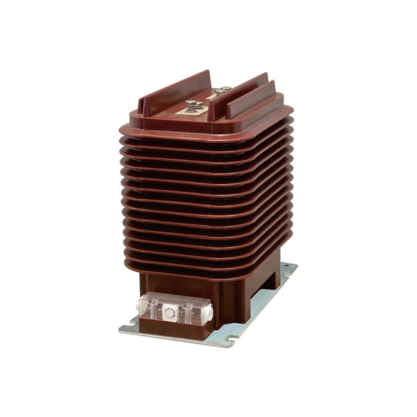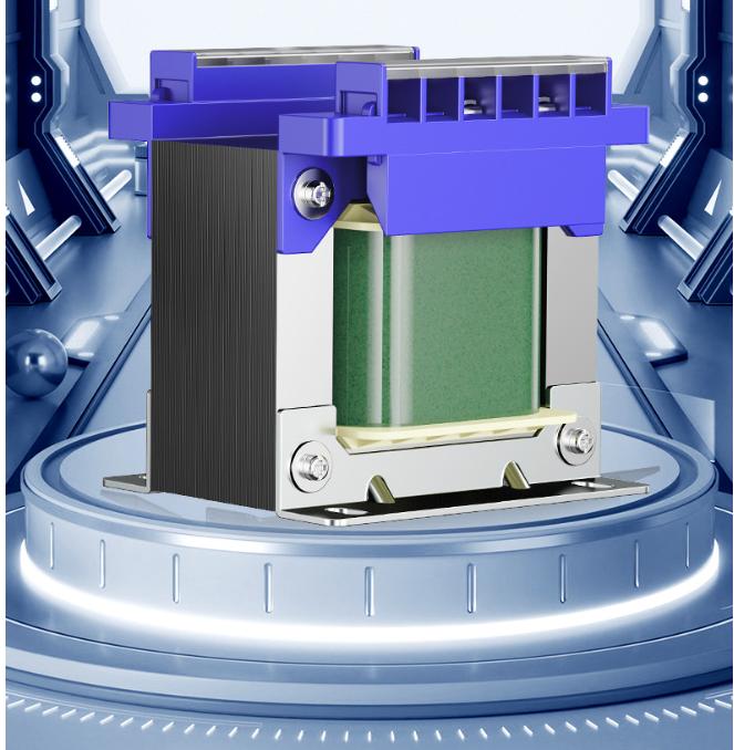
Choosing the right control transformer is not a matter of guessing, copying the last project, or simply adding up load watts. In real machine tools and industrial control panels, the transformer has to survive coil pickup, voltage fluctuation, cabinet heat, vibration, and uneven loading across multiple secondary windings.
The most common sizing mistake is also the most expensive one in the field: engineers total the load power in watts, select the nearest transformer, and assume they are done. That shortcut ignores apparent power in VA, ignores inrush current for contactors and relays, and ignores the fact that one overloaded secondary winding can fail even when the transformer’s total VA seems acceptable.
A correct control transformer sizing calculation must consider six core items: rated capacity in VA, primary voltage, secondary voltage, per-winding VA capacity, insulation class, and series/type. In practical industrial work, the rated capacity is the first checkpoint, but it is never the only one.
This guide follows the same method experienced panel builders and machine tool engineers use on actual shop-floor projects. It is especially relevant for contactor-heavy circuits, relay logic panels, solenoid valves, and mixed-voltage control systems where poor sizing causes nuisance trips, chattering coils, low secondary voltage, and overheated transformers.
Why Control Transformer Sizing Is Often Done Wrong
Most errors happen because the transformer is treated like a simple resistive power source. But control circuits are rarely resistive.
Machine tools, packaging machines, hydraulic units, and industrial control panels usually contain contactors, relays, solenoids, indicator lamps, and power supplies. These loads do not behave the same way at startup as they do in steady operation.
A contactor coil may hold at 10 to 15 VA, yet require many times that value during pickup. If the transformer cannot supply that short-duration inrush demand, the coil may not pull in cleanly. The result can be chatter, contact welding, control instability, or repeated restart attempts.
Another widespread mistake is looking only at the transformer’s total VA nameplate on a multi-output model. A transformer may be rated 250 VA overall, but if one 24 V secondary winding is rated for only 70 VA, then that 24 V winding cannot carry 120 VA just because the total transformer says 250 VA.
This is why experienced engineers do not just “add watts.” They perform a proper control circuit transformer VA rating check, review the largest coil pickup demand, and verify each secondary winding independently.
What Determines the Correct Control Transformer Size
The correct size of a control transformer is determined by a combination of electrical demand and installation conditions.
The core specifications are listed below.
Rated capacity (VA): the total apparent power the transformer can supply.
Primary voltage: must match the actual incoming industrial supply, such as AC380V or AC400V.
Secondary voltage: must match the voltage required by coils, lamps, and power supplies.
Per-winding VA capacity: each secondary winding has its own loading limit.
Insulation class: affects thermal endurance in normal or hot environments.
Transformer series/type: affects vibration resistance and suitability for machine mounting.
In practical industrial control panel transformer selection, these items are interdependent. A transformer with enough VA but the wrong voltage taps is still the wrong transformer. A transformer with the correct voltages but poor vibration resistance may fail early on a machine-mounted installation.
Control Transformer Sizing Calculation: Step-by-Step Method
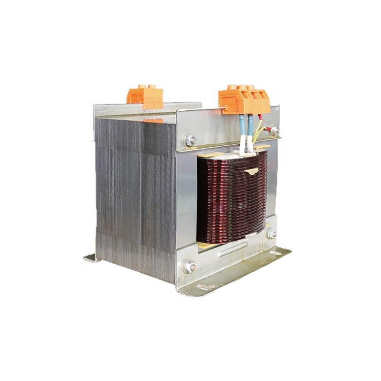
The most reliable sizing method for machine tools and control cabinets is straightforward, but it must be done carefully. You gather every real load, separate holding demand from pickup demand, apply an operating margin, and then round up to the next standard rating.
This method reflects real panel behavior better than simplistic watt-based estimates.
Step 1: List Every Load Nameplate Value
Start with the actual nameplate data for every control load. Do not estimate if the manufacturer’s VA data is available.
For each device, record the following:
Voltage
Holding VA
Pickup or inrush VA
Quantity
Which secondary winding it uses
This step matters because a good primary and secondary voltage transformer sizing process depends on knowing not just how much load exists, but where that load is connected.
Typical control loads include:
Contactor coils
Relay coils
Solenoid valves
PLC power supplies
Signal lamps
Control lighting
Interposing relays
If a datasheet gives current rather than VA, convert carefully at the rated voltage. But if the coil nameplate provides VA directly, always use the VA value.
Step 2: Calculate Total Steady-State VA
Add together all loads in their normal energized or holding condition. This gives the total steady-state apparent power, often called Ssteady.
This is the load the transformer must continuously support once all devices that are on have already pulled in.
Formula:
Ssteady = sum of all holding VA
For example, if a contactor holds at 12 VA, a PLC power supply draws 30 VA, and indicator lamps total 10 VA, all of those values belong in the steady-state total.
Step 3: Calculate Worst-Case Inrush VA
This is the step many designs skip, and it is why many panels behave poorly on startup.
In actual control systems, you usually do not add the inrush VA of every contactor coil at once. In most machine control sequences, all coils do not energize simultaneously in the same instant. The practical engineering method is to add the holding VA of all other loads plus the pickup VA of the single largest coil.
Formula:
Ssurge = all holding VA except largest coil holding replaced by largest coil pickup VA
Another way to write it:
Ssurge = (holding VA of all other active loads) + (pickup VA of the largest coil)
This method reflects field reality in machine tools and industrial controls. It is also consistent with long-standing engineering practice for contactor-based panels.
Step 4: Apply a Safety Margin Factor
After finding the larger of steady-state VA and worst-case inrush VA, apply a safety margin factor. This margin covers normal tolerance, thermal stress, supply variation, and repeated operation.
Recommended margin factors:
1.2× for ordinary machine tools and circuits that do not start and stop frequently
1.4× to 1.5× for frequent jogging, rapid cycling, or repeated solenoid switching
Do not skip this step. Even if a transformer seems adequate on paper, no margin often means lower-than-expected secondary voltage at the exact moment a coil must pull in.
Step 5: Round Up to the Next Standard VA Rating
Once the required VA has been calculated, round up to the next standard transformer rating. Never round down.
Common standard ratings are:
63 VA
100 VA
160 VA
250 VA
400 VA
630 VA
1000 VA
1600 VA
Using standard ratings simplifies procurement, replacement, and certification review. In many OEM and retrofit applications, these are the practical stocking sizes available from established manufacturers, including machine-control-focused suppliers such as Weisho Electric.
Control Transformer Sizing Formula and Quick Reference Table
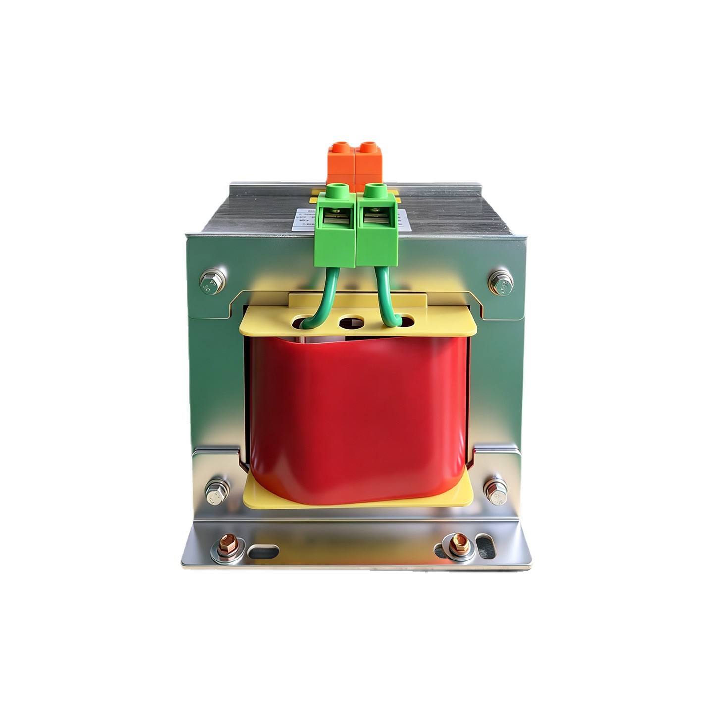
The formulas below are suitable for specification sheets, panel design reviews, and quick cross-checks during procurement.
Table: Core Sizing Formulas for Control Circuit Transformer VA Rating
| ITEM | FORMULA | MEANING |
|---|---|---|
| Steady-state VA | Ssteady = sum of all holding VA | Total apparent power during normal energized operation |
| Worst-case inrush VA | Ssurge = all holding VA except largest coil holding replaced by largest coil pickup VA | Practical startup condition for most control circuits |
| Required transformer VA | Srequired = max(Ssteady, Ssurge) × margin factor | Final basis for transformer selection |
Table: Recommended Safety Margin by Operating Condition
| OPERATING CONDITION | RECOMMENDED MARGIN | TYPICAL APPLICATION |
|---|---|---|
| Normal machine tool duty | 1.2× | General control circuits with moderate switching |
| Frequent jogging or cycling | 1.4× | Presses, indexing equipment, repeated start-stop sequences |
| Frequent solenoid switching | 1.4× to 1.5× | Hydraulic and pneumatic valve-intensive systems |
Table: Standard Control Transformer VA Ratings
| STANDARD VA RATINGS |
|---|
| 63 VA |
| 100 VA |
| 160 VA |
| 250 VA |
| 400 VA |
| 630 VA |
| 1000 VA |
| 1600 VA |
Real-World Example: How to Size a 250 VA Control Transformer
Let us walk through a realistic panel example using contactors, a PLC power supply, and indicator lights. This is the kind of mixed load arrangement seen in standard machine controls.
Table: Example Load List
| LOAD | QUANTITY | HOLDING VA | PICKUP/INRUSH VA | TOTAL USED IN CALCULATION |
|---|---|---|---|---|
| Largest contactor | 1 | 12 VA | 110 VA | 12 VA in steady state / 110 VA in surge case |
| Other contactors | 3 | 35 VA total | Not added simultaneously in this practical method | 35 VA |
| PLC power supply | 1 | 30 VA | 30 VA | 30 VA |
| Indicator lights | Multiple | 10 VA total | 10 VA | 10 VA |
Example Calculation
Ssteady = 12 + 35 + 30 + 10 = 87 VA
Ssurge = (35 + 30 + 10) + 110 = 185 VA
The larger value is 185 VA.
Apply the standard margin for an ordinary machine tool:
Srequired = 185 × 1.2 = 222 VA
Round up to the next standard size:
Select 250 VA
This is a textbook case where a small transformer chosen by steady-state power alone would fail the pickup condition. If an engineer selected a 100 VA unit based only on the 87 VA steady load, the largest contactor might never pull in reliably.
In field service, this kind of undersizing often shows up as intermittent startup, buzzing contactors, or low-voltage complaints that appear “random” until someone measures the secondary during pickup.
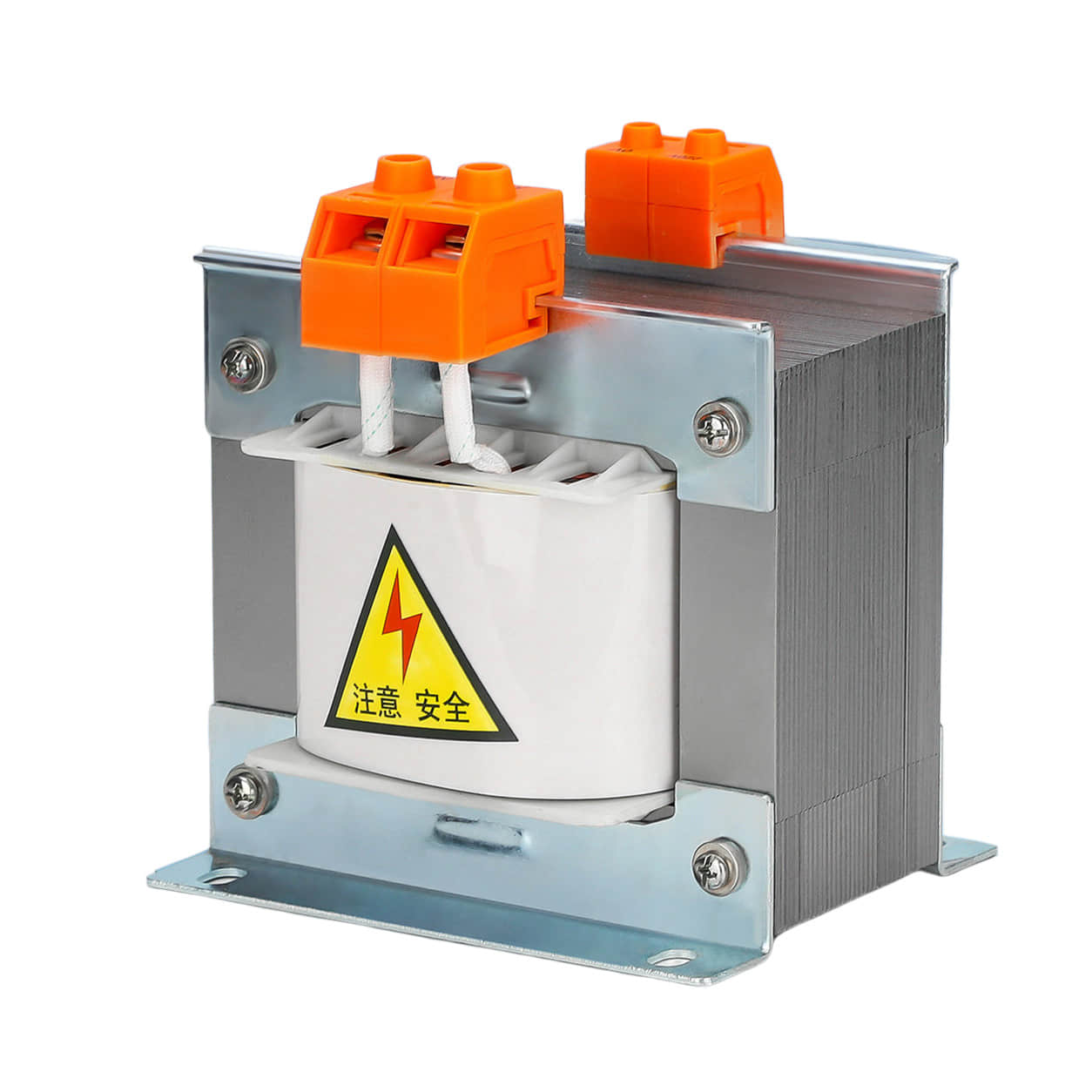
Why Inrush Current for Contactors and Relays Matters More Than Watts
Inductive control loads behave very differently from resistive heaters or incandescent loads. At the instant a contactor or relay coil energizes, the apparent power demand can be several times its holding demand.
That is why inrush current for contactors and relays is central to correct transformer selection.
Using watts instead of VA is especially dangerous in control circuits because the transformer must support magnetizing and reactive demand, not just real power. The coil may only dissipate a modest amount of heat in watts, yet still require a much higher apparent power during pickup.
In practical terms:
A coil that holds at 12 VA may require 80 VA, 100 VA, or more at pickup.
A transformer that handles the hold condition may still fail the pickup condition.
Pickup failure often causes chatter, contact bounce, or nuisance malfunction.
For this reason, a proper control transformer sizing calculation always starts from nameplate VA, never from a rough watt total.
Primary Voltage Selection for Industrial Control Panel Transformer Sizing
The primary winding must match the actual supply available at the installation site. In industrial facilities, the most common values are AC380V and AC400V, though local utility and plant distribution practices vary.
For accurate industrial control panel transformer selection, verify the real measured supply, not just the nominal plant standard written on a drawing.
Table: Common Primary Voltage Options
| PRIMARY VOLTAGE | TYPICAL USE |
|---|---|
| AC380V | Common in many industrial machine installations |
| AC400V | Common in industrial systems and export-oriented equipment |
When to Choose a Multi-Tap Primary
If the incoming line is unstable or if a machine may be shipped to sites with slightly different utility levels, a multi-tap primary is the safer choice.
Typical tap arrangement:
0-360-380-400V
This allows field adjustment to maintain a healthier secondary output. If the site supply runs low, selecting the proper tap can restore the intended control voltage without changing the transformer.
This is more than a convenience. In real plants, incoming voltage variation can be enough to push an already marginal control circuit into pickup failure. A multi-tap primary gives technicians a practical way to compensate.
Secondary Voltage Transformer Sizing by Load Type
The secondary voltage must match the actual requirement of the connected devices. There is no universal “best” secondary voltage.
Correct primary and secondary voltage transformer sizing means matching each load group to its required output and checking each secondary winding separately.
Table: Common Secondary Voltages and Typical Uses
| SECONDARY VOLTAGE | TYPICAL USE |
|---|---|
| AC110V | Legacy contactors and relay coils |
| AC220V | Contactors and power supply input |
| AC36V | Machine tool safety lighting |
| AC24V | Lighting and AC input power supplies |
| AC6.3V | Indicator lamps |
Per-Winding VA Capacity: The Most Overlooked Limit
Multi-secondary transformers are often misunderstood. Engineers see the total VA rating and assume the full capacity is available on any output winding.
That is incorrect.
Each secondary winding has its own VA limit. If the load connected to a single winding exceeds that winding’s nameplate capacity, overheating and voltage sag can occur even when the transformer’s total VA remains below the overall rating.
This point is critical in any serious control circuit transformer VA rating review.
Table: Example of Split Secondary Capacity
| TRANSFORMER MODEL | TOTAL VA | SECONDARY WINDING 1 | SECONDARY WINDING 2 | IMPORTANT NOTE |
|---|---|---|---|---|
| JBK3-250VA | 250 VA | 110V - 180VA | 24V - 70VA | The 24V winding can supply only 70VA, not the full 250VA |
This means that if your 24 V lamps, relays, and accessories total 85 VA, this transformer is already unsuitable for that winding, even though the total transformer rating is 250 VA.
On machine control projects, this specific oversight causes many avoidable field problems. It is one reason experienced buyers often ask for a winding allocation breakdown before approval. Reputable suppliers such as Weisho Electric can help confirm whether the winding split truly matches the intended load layout.
Choosing Transformer Series, Insulation Class, and Installation Conditions
Electrical calculation alone is not enough. A transformer that is correctly sized in VA can still be the wrong choice if it is installed in a high-vibration environment, hot control cabinet, or high-altitude site.
JBK3 vs JBK5 vs BK Series
For machine tool service, vibration resistance matters. Panels mounted on or near moving machinery experience more mechanical stress than a stationary wall-mounted cabinet.
JBK3 / JBK5 series: better suited for machine vibration conditions
BK series: standard type, generally less suitable for direct machine-body mounting
If the transformer will be installed on equipment subject to impact, spindle vibration, or repeated motion, JBK3 or JBK5 is usually the better engineering choice.
Insulation Class Selection
Insulation class should reflect real operating temperature, not just ambient room temperature.
Class F, 155°C: suitable for normal workshops and standard control cabinets
Class H, 180°C: better for 24-hour continuous operation or high cabinet temperatures
In a tightly packed enclosure with drives, braking resistors, or poor ventilation, upgrading insulation class can materially improve durability and service life.
Mounting and Environmental Limits
As a general rule, mount the transformer on the control cabinet backplate or baseplate rather than directly on the machine bed. This reduces transmitted vibration.
Other practical rules include:
Avoid direct installation where coolant spray, oil mist, or metal dust is severe unless the enclosure design addresses it.
Derate the transformer for installation above 2000 m altitude.
Review cabinet temperature under full-load summer conditions, not just room-temperature commissioning.
These installation details often separate a durable design from one that works only during initial factory testing.
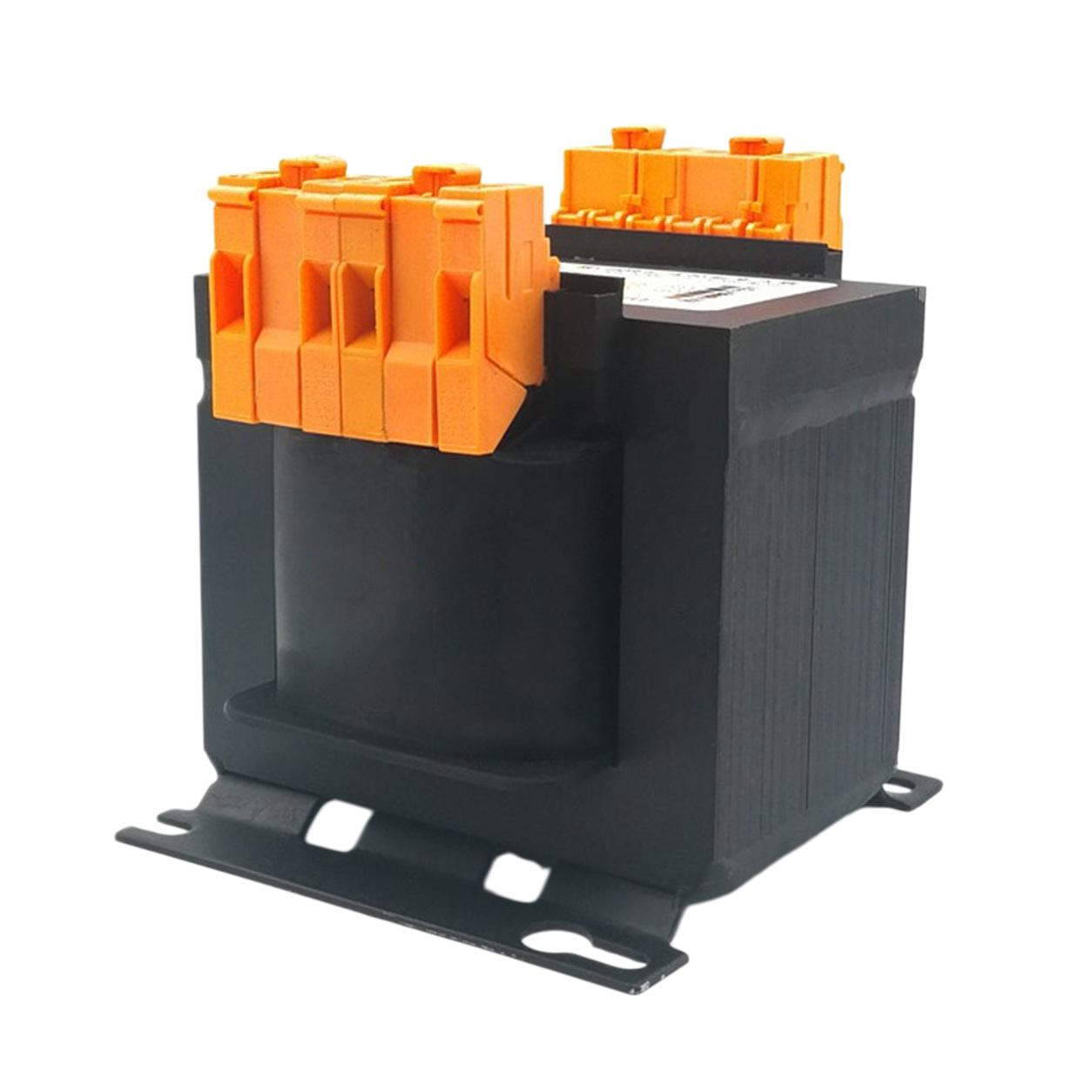
Final Checks Before You Approve a Control Transformer
Before releasing a design, issuing a purchase order, or approving a substitute part, perform a final validation. This last review prevents most common field failures.
Table: Common Control Transformer Sizing Mistakes
| MISTAKE | WHY IT CAUSES PROBLEMS |
|---|---|
| Using W instead of VA | Inductive loads are sized by apparent power, not real power alone |
| Ignoring inrush current | Pickup voltage may collapse and coils may chatter or fail to energize |
| Ignoring per-secondary VA limits | One winding may overload even if total transformer VA appears acceptable |
| Forgetting voltage drop | Long wiring runs reduce delivered voltage to coils and lamps |
| No safety margin | Small supply variations or repeated duty can push the transformer beyond safe performance |
| No tap allowance | There is no easy field correction for low or high supply conditions |
Verify Secondary Voltage Drop Under Worst-Case Pickup Load
Under the maximum inrush condition, the secondary voltage should not fall below 85% of rated secondary voltage.
This is a practical and important acceptance criterion. If the voltage sags below that threshold during coil pickup, contactors may buzz, pull in weakly, or fail to seat fully.
Allow for Cable Drop and Future Adjustment
If there are long cable runs between the transformer and the actual load, include a voltage correction strategy. Even a correctly sized transformer can deliver marginal voltage at the device after wiring losses.
Where needed, provide ±5% output taps for field adjustment. This is especially helpful for remote operator stations, machine lighting circuits, or legacy equipment with stricter coil tolerance.
Confirm Grounding and Isolation Safety
Check that grounding terminals are complete and that the transformer meets the required isolation and safety standards for the panel or machine.
Do not treat this as an afterthought. Proper grounding and isolation are fundamental to personnel safety, fault containment, and compliance review.
Control Transformer Selection Checklist
For procurement and design review, a concise checklist prevents surprises. It also makes supplier communication faster and more accurate.
Table: Control Transformer Selection Checklist
| CHECKLIST ITEM | WHAT TO CONFIRM |
|---|---|
| Required VA rating | Based on max of steady-state and worst-case surge, then margin applied |
| Safety margin factor | 1.2× normal duty, 1.4× to 1.5× frequent cycling duty |
| Primary voltage and taps | AC380V, AC400V, or multi-tap such as 0-360-380-400V |
| Secondary voltages | Match each load group exactly |
| Per-winding VA allocation | Each secondary winding checked independently |
| Transformer series | JBK3/JBK5 for vibration-prone machine service |
| Insulation class | F class 155°C or H class 180°C depending on thermal duty |
| Mounting location | Prefer cabinet backplate or baseplate, not machine bed |
| Altitude/temperature conditions | Derate above 2000 m and review hot-cabinet operation |
| Grounding/isolation requirements | Complete grounding terminals and required isolation compliance |
If you follow this checklist, your control transformer selection will be based on real operating conditions rather than optimistic assumptions.
FAQ
How do I calculate the correct VA rating for a control transformer?
Start by summing all holding loads to get steady-state VA. Then calculate the worst-case surge by adding the pickup VA of the single largest coil to the holding VA of the other active loads. Take the larger of those two values, multiply by an appropriate margin factor, and round up to the next standard transformer size.
Can I size a control transformer by adding load watts?
No. Control circuits with contactors, relays, and solenoids must be sized using apparent power in VA, not just watts. Using watts alone ignores reactive demand and often leads to undersized transformers.
Do I need to add the inrush current of every contactor coil?
In most industrial control systems, no. The standard practical method is to add the pickup VA of the single largest coil to the total holding VA of the remaining loads, because all coils rarely energize at exactly the same instant.
How do I size a control transformer with multiple secondary windings?
Each secondary winding must be matched to the required output voltage and checked against its own VA limit. You cannot rely on the transformer’s total VA rating alone if one winding has a lower individual capacity.
What primary voltage should I choose for a control transformer?
Choose a primary voltage that matches the actual site supply, such as AC380V or AC400V. If plant voltage fluctuates or the machine may be installed in different locations, a multi-tap primary is the better choice.
What happens if a control transformer is undersized?
The secondary voltage may sag during coil pickup, causing contactors to chatter or fail to pull in. Over time, the transformer may also run hot, age faster, and become a recurring reliability problem in the panel.
Is a 250 VA control transformer enough for my panel?
It depends on the largest coil pickup VA, the total holding VA, the duty cycle, and how the loads are distributed across the secondary windings. A 250 VA transformer may be sufficient in one panel and completely inadequate in another with the same steady-state load.
Get Help Selecting the Right Control Transformer
If you want a reliable recommendation, do not send only the total panel wattage. Send the real load list.
Include your coil voltages, holding VA, pickup VA, quantity of each device, primary supply voltage, required secondary voltages, and duty cycle. With that information, a proper industrial control panel transformer selection can be made quickly and accurately.
Need a fast answer? Share your panel load schedule, winding requirements, and operating conditions now, and get a precise control transformer recommendation instead of a risky guess. Choose a transformer that will pull in cleanly, run cooler, and last longer in real service.
Contact us today for expert sizing support and product guidance on the right control transformer for your machine or panel.