They often look almost the same at first glance, but wiring one incorrectly can create voltage problems, nuisance trips, excess harmonics, or even a serious shock hazard.
Many electricians, maintenance technicians, and panel builders confuse a reactor with an isolation transformer or mistake a control transformer for an isolation unit because all three are coil-based magnetic devices. The truth is simple: one limits current, one changes voltage, and one isolates for safety and noise control.

Why Do Reactors, Isolation Transformers, and Control Transformers Look Similar but Work So Differently?
All three devices are built around copper windings and magnetic cores, so from the outside they can appear nearly identical in a cabinet or on a repair bench.
But their internal structure, grounding method, and electrical purpose are very different. That difference directly affects installation safety, equipment reliability, and system performance.
The Real Problem: Misidentifying These Devices Can Cause Safety and Performance Issues
Using the wrong device can lead to the wrong output voltage, poor control circuit operation, excessive electrical noise, or a dangerous false assumption about shock protection.
For example, installing a reactor where an isolation transformer is needed will not provide electrical separation. Installing a control transformer where harmonic suppression is needed will not limit current the way an electrical reactor functions in power systems is designed to do.
Quick Visual Identification: How to Tell Them Apart at a Glance
In the field, fast identification matters. The easiest first check is the number of terminals and whether the device has a single winding or separate primary and secondary windings.
Reactor: Two Terminals, Single Winding, No Voltage Conversion

A reactor usually has only 2 terminals and a single winding. There is no primary-secondary structure.
Some small reactors even show an exposed coil. A reactor is a pure inductive component, so it does not step voltage up or down and does not provide electrical isolation.
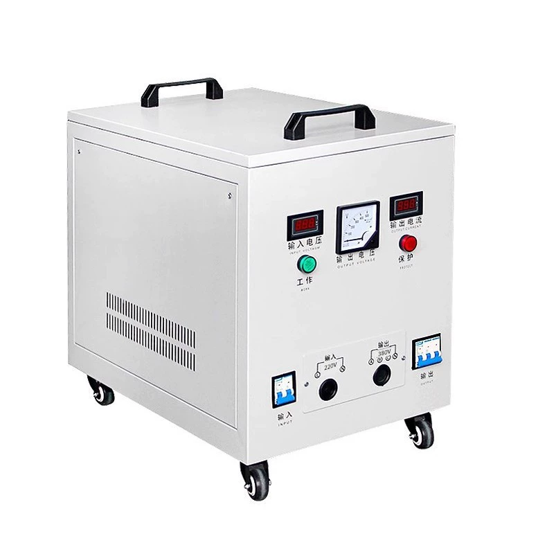
Control Transformer: Multiple Input/Output Terminals for Voltage Conversion

A control transformer normally has separate input terminals and multiple output taps. Typical ratings include 380V or 220V input and 220V, 36V, 24V, or 6.3V outputs.
Its winding structure is dual winding: primary plus secondary. In standard machine-tool practice, the metal enclosure must be grounded.
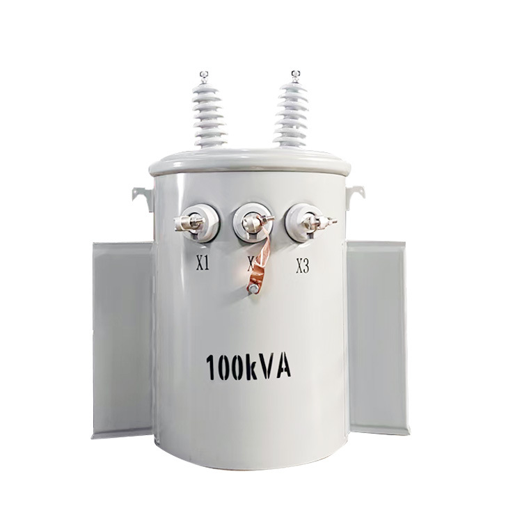
Isolation Transformer: Input and Output Terminals with 1:1 Ratio and Shielding

An isolation transformer also has separate input and output terminals, but its standard arrangement is usually a 1:1 voltage ratio, meaning input and output voltage are approximately equal.
Its distinctive feature is an electrostatic shield between primary and secondary windings. The secondary side is typically kept floating relative to ground.
Comparison Table: Reactor vs Isolation Transformer vs Control Transformer
| Feature | Reactor | Control Transformer | Isolation Transformer |
|---|---|---|---|
| Basic structure | Single winding | Primary + secondary windings | Primary + secondary windings |
| Typical terminal count | 2 terminals | Input terminals + multiple output taps | Separate input and output terminals |
| Changes voltage | No | Yes | Usually no, commonly 1:1 |
| Electrical isolation | No | Yes, by transformer structure, but not its main purpose | Yes, the main purpose |
| Electrostatic shield | No | Usually no | Usually yes |
| Grounding characteristic | Depends on installation | The metal enclosure must be grounded | Secondary typically floating |
| Main purpose | Current limiting, harmonic suppression | Control voltage conversion | Shock protection and noise reduction |
| Typical use | VFDs, servo drives, power cabinets | Machine tools, PLC panels | Medical, lab, repair bench, precision equipment |
What Is a Reactor in Electrical Systems?

A reactor is an inductor used to control current behavior in AC or DC-related power circuits. The electrical reactor function in power systems is primarily to limit inrush or fault current, suppress harmonics, and smooth current changes.
It is not a transformer. It has no secondary winding and no voltage transformation role.
Reactor Working Principle: Self-Inductance in a Single Winding
A reactor works by self-inductance. When the current tries to change rapidly, the magnetic field in the winding opposes that change.
This opposition is inductive reactance, not primary-to-secondary energy transfer. That is why a reactor can slow current rise and reduce current distortion, but cannot perform transformer-style voltage conversion.
Main Reactor Applications in Industry
VFD input line reactors to reduce line harmonics and protect the front end of the drive
VFD output load reactors to reduce motor cable stress and smooth PWM current
Servo drive systems for current conditioning
Motor soft-start circuits for current limiting
Power distribution cabinets for short-circuit current limiting
Harmonic mitigation systems in industrial plants
In real installations, a 3% line reactor is a common accessory for industrial variable frequency drives. In many factory drive systems, this small impedance addition can help reduce nuisance tripping and improve power quality under unstable supply conditions.
What Is a Control Transformer?

A control transformer is a transformer built to supply the correct voltage for machine control circuits. Its main job is to step voltage down or up so relays, contactors, PLC inputs, lamps, and solenoids receive the rated control voltage.
This is why control transformer applications are common in industrial automation and machine tools.
Control Transformer Working Principle: Electromagnetic Induction Between Primary and Secondary
A control transformer works by electromagnetic induction. AC voltage on the primary creates a magnetic flux in the core, which induces voltage in the secondary winding.
The output voltage depends on the turns ratio. If the transformer is designed for 380V to 24V, the winding ratio is set specifically for that conversion.
Common Control Transformer Applications
Machine tools and CNC equipment
PLC control panels
Contactors and relays
Indicator lamps
Solenoid valves
Electromagnetic control circuits
A standard BK machine control transformer often converts 380V or 220V to 24V or 36V. These are widely used because many control devices are designed for safer and more stable low-voltage operation.
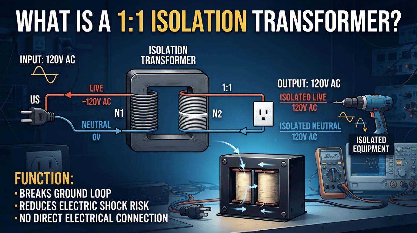
What Is an Isolation Transformer?

An isolation transformer is designed to provide full electrical separation between the power source and the load. The isolation transformer working principle is based on energy transfer through magnetic coupling while keeping the primary and secondary electrically disconnected.
In most practical installations, the turns ratio is 1:1, so voltage remains roughly the same while safety isolation is added.
Isolation Transformer Working Principle: 1:1 Voltage Ratio with Full Electrical Isolation
The primary winding receives the incoming supply, and the secondary winding delivers power to the load without a direct conductive path between them.
This means the output can be electrically separated from the mains ground reference. That is the key reason isolation transformers are used for safer troubleshooting, reduced ground-loop issues, and protection of sensitive devices.
Why Isolation Transformers Include an Electrostatic Shield
Many quality isolation transformers include an electrostatic shield between windings. This shield helps block high-frequency common-mode noise from coupling from the input side to the output side.
That is especially valuable for precision electronics, medical devices, bench testing, and any application where noise immunity matters.
Typical Isolation Transformer Applications
Medical equipment
Precision instruments
PCB repair stations
Welding equipment
Laboratory test benches
Maintenance and troubleshooting benches
On a repair bench, a 1:1 isolation transformer is often used before energizing a board under test. It does not make unsafe work safe by itself, but it does reduce the hazard of direct reference to the mains supply.
Control Transformer vs Isolation Transformer: What Is the Difference?
This is one of the most searched comparisons because both devices have primary and secondary windings. Still, their design priorities are not the same.
The differences between control and isolation transformers come down to purpose, grounding behavior, and output arrangement.
Voltage Conversion vs Electrical Isolation
A control transformer mainly exists to provide the correct control voltage. It may step down from 380V to 24V, or from 220V to 36V, depending on machine needs.
An isolation transformer mainly exists to create a safer, electrically separated supply and reduce common-mode interference. In most cases, it does not aim to change the voltage significantly.
Grounding Difference: Earthed Enclosure vs Floating Secondary
For a control transformer, the metal enclosure should be grounded as standard installation practice. This improves operator safety and fault protection.
For an isolation transformer, the secondary is typically left floating with respect to ground. That floating condition is part of why single-point contact with one secondary conductor generally presents lower shock risk than contact with a live conductor referenced directly to earth.
Reactor vs Isolation Transformer: Why They Are Not Interchangeable
A reactor and an isolation transformer may both include coils and cores, but they are fundamentally different devices.
A reactor is an inductor for current control. An isolation transformer is a transformer for safe isolation and noise reduction. One cannot substitute for the other without losing the intended function.
Reactor vs Control Transformer: Single Winding vs Dual Winding Design
A reactor has a single winding and is built to oppose current change. It cannot step voltage up or down.
A control transformer has dual windings and is built specifically for voltage transformation. If you need 24V control power from a 380V supply, a reactor cannot do that job.
Data Table: Real-World Examples of Ratings, Uses, and Typical Installations
| Device | Typical Rating Example | Typical Installation | Practical Purpose |
|---|---|---|---|
| Line reactor | 3%, 380V, matched to VFD input current | Factory VFD panel | Reduce harmonics, limit inrush, protect drive |
| Load reactor | Output reactor sized to motor current | Long motor cable installation | Smooth current and reduce reflected-wave stress |
| BK control transformer | 380V to 24V, 100VA to 500VA common range | CNC machine or PLC cabinet | Supply low-voltage control devices |
| Multi-tap control transformer | 380V/220V input, 220V/36V/24V/6.3V outputs | Machine tool control panel | Serve multiple control voltage needs |
| Isolation transformer | 1:1, 220V to 220V, 500VA to 2kVA bench units | Electronics repair bench | Separate equipment from mains for safer service |
| Medical isolation transformer | 1:1 with shield and strict leakage design | Medical equipment supply system | Improve patient/operator protection and noise control |
Safety Table: Grounding, Shock Risk, and Installation Notes
| Device | Enclosure Grounding | Output/Secondary Ground Reference | Shock Risk Note | Installation Note |
|---|---|---|---|---|
| Reactor | As required by equipment design | Not applicable as transformer secondary | Does not provide touch protection by isolation | Match current, impedance, and system voltage |
| Control transformer | The metal enclosure must be grounded | Depends on circuit design | Primary hazards remain if wired incorrectly | Select the correct primary taps and output voltage |
| Isolation transformer | Enclosure grounded | Secondary typically floating | Single-conductor contact risk is reduced, but not to zero-risk work | Do not defeat isolation by improper secondary grounding unless system design requires it |
Practical Selection Guide: Which One Should You Choose?
The right choice depends on the actual job to be done. Ask one question first: Do you need current limiting, voltage conversion, or electrical isolation?
Choose a Reactor If You Need Current Limiting or Harmonic Control
Use a reactor when your goal is to control current behavior, reduce harmonic effects, or smooth current transitions in power electronics.
VFD panels
Servo drives
Motor circuits
Power cabinets with harmonic concerns
Short-circuit current limiting applications
Choose a Control Transformer If You Need Lower or Multiple Control Voltages
Use a control transformer when your equipment needs a specific machine control voltage.
PLC cabinets
Machine tools
24V or 36V control loops
Contactor coils
Indicator lamps and solenoids
Choose an Isolation Transformer If You Need Shock Protection and Noise Reduction
Use an isolation transformer when safety separation and interference reduction matter more than changing voltage.
Repair benches
Laboratories
Medical systems
Sensitive electronics
Precision instruments
Real-World Data and Examples: Where Each Device Is Commonly Used
In industrial factories, reactors are frequently installed with variable frequency drives because harmonics, inrush current, and motor cable effects are everyday issues.
In CNC and PLC control panels, control transformers are standard because field devices commonly require 24V or 36V rather than line voltage.
In electronics repair and laboratory environments, 1:1 isolation transformers are common because technicians need a floating secondary for safer troubleshooting and lower common-mode noise.
Field rule of thumb: if it has only two terminals and one coil, think reactor. If it has primary and secondary taps for different voltages, think control transformer. If it is 1:1 and built for a floating secondary with shielding, think isolation transformer.
Common Mistakes When Identifying Reactors and Transformers
Assuming every coil-based device changes voltage
Ignoring the difference between single-winding and dual-winding construction
Confusing a 1:1 isolation transformer with a standard control transformer
Overlooking the electrostatic shield in the isolation transformer design
Incorrectly grounding the secondary of an isolation transformer and defeating the floating benefit
Selecting a control transformer when the real issue is harmonics or current limiting
Expecting a reactor to provide electrical isolation

FAQ
What is the main difference between a reactor and an isolation transformer?
A reactor limits or smooths current through inductance, while an isolation transformer provides electrical separation between input and output without significantly changing voltage in typical 1:1 designs.
What is the difference between control and isolation transformers?
Control transformers are mainly used for voltage conversion in machine control circuits, while isolation transformers are mainly used for safety isolation and interference reduction.
Can a reactor change voltage like a transformer?
No. A reactor has only one winding and does not perform primary-to-secondary voltage transformation.
Why does an isolation transformer usually use a 1:1 ratio?
Its main goal is to keep the voltage approximately the same while electrically separating the load from the power source.
Why must a control transformer enclosure be grounded?
Grounding the metal enclosure improves operator safety, supports fault protection, and follows standard installation practice for industrial control equipment.
Is an isolation transformer safer against electric shock?
Its floating secondary can reduce shock risk in single-point contact situations, but it does not eliminate all hazards. Safe work procedures, proper testing, and correct installation are still essential.
Where are control transformers most commonly used?
They are commonly used in machine tools, PLC panels, relays, contactors, indicator lamps, and solenoid valve circuits.
Where are reactors most commonly used in power systems?
They are commonly used with VFD systems, servo drives, harmonic filtering setups, motor circuits, and short-circuit current limiting in electrical cabinets.
Conclusion: One Looks Like a Coil, One Changes Voltage, One Isolates for Safety
Reactors limit current, control transformers adapt voltage, and isolation transformers protect through electrical separation.
Need Help Choosing the Right Device for Your Panel or Project?
Do not guess from appearance alone. Compare the terminals, winding structure, voltage function, and grounding method before you wire or buy.
Share your application, panel voltage, load type, and safety requirements with a qualified supplier or engineer today to get the right reactor, control transformer, or isolation transformer selection, wiring guidance, and custom specification support.