Previous
Next
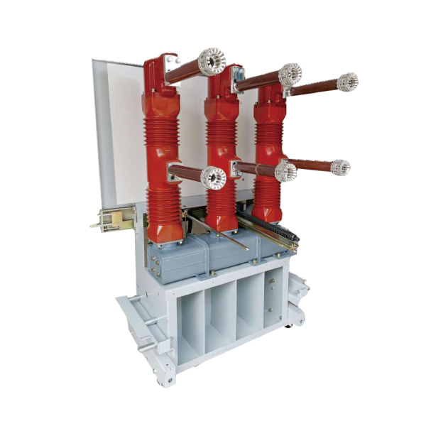
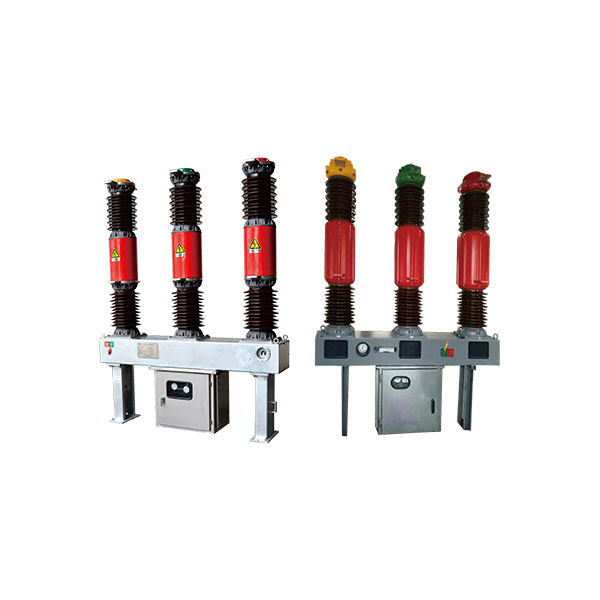
LW36-72.5/126 Outdoor High-Voltage Vacuum Circuit Breaker
Overview
The LW36 - 126 outdoor high-voltage sulfur hexafluoride circuit breaker stands as a reliable three-phase AC 50Hz outdoor high-voltage switchgear. Engineered for the control and protection of 126 kV power transmission and transformation systems, it also excels in contact breaking and opening/closing operations. Employing the "thermal expansion + blowing aid" principle for arc extinguishing, this circuit breaker comes paired with a CTB - 1 spring - operated mechanism. It complies with the stringent GB1984 - 2003 standard for AC high-voltage circuit breakers and meets the international requirements set by IEC62271 - 100:2001 for high-voltage switchgear and controlgear. Notable features of the LW36-126 include its self-energy arc extinguishing mechanism, which ensures outstanding breaking performance, a short arc-burning time, an extended electrical lifespan, and minimal operating noise. Utilizing SF6 gas, renowned for its superior insulation and arc - arc-extinguishing capabilities, it eliminates the risk of combustion and explosion, making it a safe choice even for use in densely populated areas. The spring actuating mechanism contributes to its simple yet compact design, guaranteeing safe and reliable operation. In terms of environmental suitability, the circuit breaker functions optimally within an ambient temperature range of - 30℃ to + 40℃, with special configurations available for - 40℃ to + 40℃ environments. It can be installed at altitudes of up to 4000m. It withstands relative humidity levels where the daily average doesn't exceed 95% and the monthly average at 25°C stays below 90%, with a saturation vapor pressure limit of 2.2×10 - 3 MPa. The equipment endures wind pressures of up to 700 Pa, ice cover thicknesses of 10 mm, and seismic forces with horizontal acceleration of ≤0.3g and vertical acceleration of ≤0.15g. It can tolerate sunlight intensities of 0.1 W/cm² (at a 0.5 m/s wind speed) and daily temperature differences of up to 25°C. With a nominal creepage ratio distance of 31mm/kV, it's designed to operate in areas free from flammable, explosive, chemically corrosive, or violently vibrating conditions.
Main technical parameters
| serial number | Item | unit (of measure) | Technical Parameters | |
| 1 | rated voltage | KV | 126 | |
| 2 | Rated frequency | Hz | 50 | |
| 3 | rated current | A | 3150 | |
| 4 | Rated short-circuit breaking current | short-circuit current | kA | 31.5 |
| DC component | - | 40% | ||
| 5 | Rated short circuit duration | s | 4 | |
| 6 | Rated for short-time withstand current | kA | 40 | |
| 7 | Rated short-circuit closing current (peak) | kA | 100 | |
| 8 | Rated peak withstand current | 100 | ||
| 9 | Rated 1min frequency withstand voltage (RMS) | Concerning the ground, between phases | kV | 230 |
| between contacts | 265 | |||
| 10 | Rated lightning impulse withstand voltage (peak) | Concerning the ground, between phases | 550 | |
| 650 | ||||
| 11 | 5min zero gauge pressure withstand (RMS) | between contacts, concerning the ground | 95 | |
| 12 | Rated out-of-step breaking current | kA | IeX25% | |
| 13 | Near-area fault opening current | IeX90%,IeX75% | ||
| 14 | Rated line charging breaking current | A | 50 | |
| 15 | Rated sequence of operation | - | O-0.3s-CO-180s-CO | |
| 16 | First open pole factor | - | 1.5 | |
| 17 | Closing time | ms | ≤100 | |
| 18 | Split time | 30≤t≤45 | ||
| 19 | breaking time | ≤60 | ||
| 20 | Opening and closing times | 60 | ||
| 21 | Opening synchronization | 4 | ||
| 22 | Closing synchronization | 5 | ||
| 23 | Rated SF6 gas pressure (20°C) | Mpa | 0.60 | |
| 24 | Annual SF6 gas leakage rate | - | ≤0.5% | |
| 25 | Gas Moisture Content | ppm (v/v) | ≤150 | |
| 26 | radio interference level | μV | ≤2500 | |
| 27 | Mechanical life span | times | 6000 | |
| 28 | Quality per breaker | kg | 1400 | |
| 29 | Mass of SF6 gas per unit | 6 | ||
| 30 | Main circuit resistance per pole | μΩ | 70 | |
1.4.1 The main technical parameters of the circuit breaker are shown in Table 1.
| serial number | Item | unit (of measure) | digital | Remarks |
| 1 | Dynamic contact travel | mm | 130+2-3 | |
| 2 | Angle Stroke | 27±2 | ||
| 3 | Spring Mechanism Stroke | 1000-3 | ||
| 4 | Clearance between arm rollers and mechanical cams | 1.4±0.3 | Breaker in open state, closing spring energized. | |
| 5 | Distance between the closing spring locating nut and the locating rod B | 12~47 | ||
| 6 | Closing solenoid travel C | 5.0~5.5 | Circuit breaker in open state | |
| Trigger and release gap D | 2.0~2.5 | |||
| C-D | 3.0~3.5 | |||
| 7 | Split solenoid travel F | 2.8~3.2 | Circuit breaker in closed state | |
| Trigger and release gap G | 0.8~1.2 | |||
| F-G | 1.6~2.4 |
1.4.2 Control loop and auxiliary loop parameters in Table 3
| serial number | Item | unit (of measure) | Remarks | ||
| 1 | Switching and closing the circuit control voltage | v | DC220 | DC110 | |
| 2 | Switching coil current | A | 小于2.3 | 5.5 | |
| 3 | Closing coil current | A | 2 | 3.5 | |
| 4 | Energy Storage Motors | Supply Voltage | V | DC220(110)/AC220 | |
| Normal operating voltage range | - | 65%~110% | |||
| power (output) | W | 450 | |||
| Energy storage time | s | ≤15 | |||
| number of revolutions per minute | r.p.m | 750 | |||
| amps | A | 3.6 | 5.5 | ||
| 5 | The heater has a lighting circuit voltage | V | AC220 | ||
| 6 | Heater power | W | 100 | ||
1.4.3 SF6 gas pressure parameters are given in Table 4 (20°C).
| serial number | Item | unit (of measure) | Remarks |
| 1 | Rated inflation pressure | Mpa | 0.6 |
| 2 | Charge Air Alarm Pressure | 0.55±0.03 | |
| 3 | lockout pressure | 0.50±0.03 |
Product structure and principle
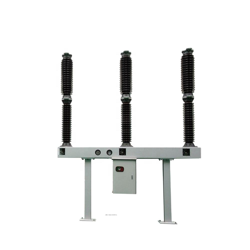
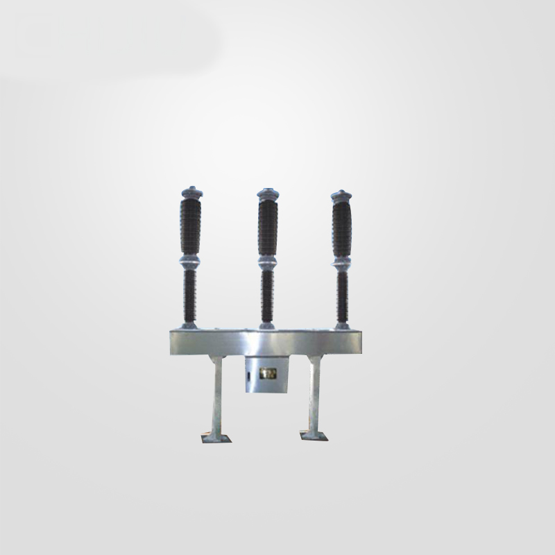
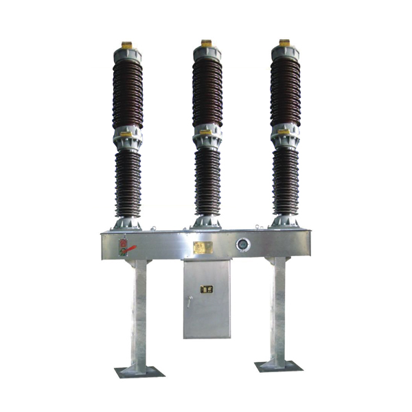
2.1 General Structure and Principle The product features an overall structure that incorporates a self-energizing arc extinguishing chamber. Each pole is a single column with a single interrupter, simply called a pole. Every circuit breaker is composed of three such poles, which are mounted on the same frame. They are operated by a spring mechanism, and there is a mechanical linkage among the three poles. At the upper part of the product lies the ceramic sleeve of the arc extinguishing chamber. The middle section consists of the pillar ceramic sleeve and the frame. The mechanism box is centrally positioned and suspended beneath the frame. Inside this mechanism box, a spring-operated mechanism and the electrical control part are installed. The output tie rod of the mechanism is connected to the actuating arm of B. The SF6 gas density controller is placed on the front side of the frame, and both ends of the frame are supported by pillars. In terms of the control principle, there are two distinct schemes: the single-split circuit and the double-split circuit. For reference, Annex III: Electrical Control Schematic and Annex IV: Secondary Wiring Diagrams are based on the double-split circuit. However, the engineering agreement takes precedence, and the corresponding electrical control schematic and secondary wiring diagrams will be provided along with the product as per the specific requirements.

The components of the circuit breaker include: 1. Single-pole circuit breakers (poles) 2. Frames 3. Nameplates 4. Density controllers 5. Gas fills and inspection ports 6. Mechanism boxes 7. Poles As depicted in Figure 1 depicts the overall structure of the circuit breaker. **2.1.1 Single-pole Circuit Breakers** 2.1.1.1 The structure of the single-pole circuit breaker is presented in Figure 2. **Packaging and Documentation** - Packing list: One copy is provided. It details all the items included in the shipment of the circuit breaker, helping with inventory and verification during receipt. - Electrical control principle diagram and secondary wiring diagram: Each comes in one copy. These diagrams are crucial for understanding the electrical operation and wiring connections of the circuit breaker, which are essential for installation, maintenance, and troubleshooting. - Product qualification certificate: One copy serves as proof that the product meets the specified quality and performance standards. - Factory inspection report of the product: One copy documents the tests and inspections carried out at the factory before the product is shipped, ensuring its compliance with relevant regulations and requirements. - On-site installation inspection test report (see Appendix I, to be filled): Two copies are provided. This report is used to record the inspections and tests conducted during the on-site installation process, ensuring that the circuit breaker is installed correctly and functions properly. Please note that this is a more detailed and organized presentation of the given information, highlighting the importance of each component and document. If you need any further modifications or have other requirements, feel free to let me know.
Contact Us
Related Products